


Patents Completed.
Page 26
If you've noticed an error in this article please click here to report it so we can fix it.
STEAM ENGINE—Leon Sem°IleaNo. 17,549, dated August 3rd, 1906.—The moving parts of the engine, such as the shaft, crank, connecting rods, valveshafts, etc , are separated from thc hot cylinder so that the oil required for those parts remains cool, and, being confined
in a casing, leakage or less of oil is impossible. This is effected by providing, instead of the usual stuffing box, a guide (d), which is carried by the extension (I), which also serves as a cylinder cover. The guide (d) is provided with internal parallel grooves, and the one nearest to the cylinder cemmunicates to a force feed lubricator, by means of a passage (g). The steam that leaks into this first groove forces the oil into the next, and so on through each succeeding groove unlit it emerges into the extension (j), and provides lubricant for the circular crosshead tki. Any surplus ail or steam escapes by a pipe ,77! to an outlet (1). The oil for the other moving parts is carried in a hermetically-sealed crankcase (p), where it remains cool and retains its full lubricating properties, being unable to come into contact with the hot cylinder walls cr with any escaping steam
WATER EjECTOR.—G. H. le Grys.— No. 12,234, dated May 25th, 1906.—The invention claims to prevent the collection of mud or sediment in the globular nozzle chamber, should dirty water be used. Water is admitted either at the side or from below the globular chamber (B).
Steam is admitted by means of a detachable nozzle (Ea, having rounded outer surface (F) and an inclined conical outlet (0). The delivery branch (I.) has a flared lower end, upon which some of the issuing steam impinges, and is deflected back into the chamber, and creates a swirling motian therein This swirling !notion tends to prevent the co:lection of any sediment which might be carried in the water. When the water is arranged to enter the chamber from .below the steam nozzle is arranged as shown in Fig. 2.
IMPROVED BOILER TUBE.-17. Lejeune and J. Pikal.—No. 12,315, dated May 20th, 1906.—Tbe main portion of the tube is made of steel, with walls (1, I) as thin as possible, while the ends (2,2) of the tube which enter the tube plates are made of wrought iron, with walls of greater thickness. These ends are welded to the body of the tube. It is claimed that tubes made in the above manner, by reason of the great thickness of the ends and of their relatively soft state, can be easily expanded, v,,hilst the thin parts of the tubes admit of a rapid exchange of heat, thereby lengthening their life. The insertion and withdrawal of the tubes is also rendered much easier, as the ends, being, as dektibed., relatively soft, the holes in the tube plate are not injured during such operation.
DUST COLLECTOR.—W. G. Weaver. —No. 2,004, dated October 28th, 1905.—
The body of the fan is provided with intakes (At, to which are attached flaps or extensinns (A2) for collecting the dustladen air. The boss (C) of the fan consists of a hollow annular chamber, into which is sprayed a supply of liquid, which enters by means of a pipe (E2) and the hollow shaft (E). The boss (C!) is surrounded by two metallic gauze drums (Cl, C21, the space between the drums being filled with absorbent material, which is kept constantly moistened by the liquid issuing from the holes (0). As the fan is revolved by the driving pulley (F) a spray is thus flung off from the absorbent material by centrifugal force. This spray mixes with the dust in the air, which is precipitated in the form of mud through the outlet (B).
ADJUSTABLE VALVE ROD.—Johnson.--No. 13,121, dated June 6th, 1906.— In order that the valve-rod may be precisely adjusted to ensure perfect action of the engine, the rod (3) is made hollow, and is screw-threaded at its upper end to receive a plug (7). The plug carries a striking head (9), whereby the valve stem (101 is lifted as the rod rises under the action of its operating cam. The upper end of the rod is split, and a jamb-nut
(14) is provided, whereby the plug (7) is rigidly held in position after adjustinent.
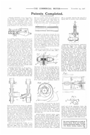
VARIABLE FRICTIONAL DRIVING GEAR.—R. Hagen,—No. 3,231, dated February 9th, 1906. Date claimed under iete:national Convention, April 15th, 1905. —The engine shaft (b.) carries a conical drum (c), and a male portion (d) of a clutch, the other portion of the clutch )1) being connected by a cardan shaft to the driving wheels, A second conical drum (e) is mounted parallel to the first, and carries an endless belt (el), which can be made to contact with the drum (c) by moving the axle (g) nearer to that of the drum (c). This is accomplished by a foot pedal (7). In starting the vehicle the part (1) is declutched from the part (1), and the drum (e) is made to rotate the drum (e) by the belt (el). The axle (g) carries a pulley (h), which is engaged with the member (i) of the clutch by an endless band (k). When the belt has reached the small end of the subsidiary drum, the driven shaft (a) is revolving at the same speed as the driving shaft (b), and the clutch is caused to come into operation, he drum being then thrown out of engagement. A reverse is provided by placing the belt (d) on the cylindrical portion of the drum, and forcing a friction wheel r) into engagement with both drums.