


Steam as a Motive Power for Public Service Vehicles:
Page 22
Page 23
Page 24
If you've noticed an error in this article please click here to report it so we can fix it.
Starting up.—The simple and expeditious starting of the burner has received much attention. The preliminary heat
ing was originally done by burning methylated spirit. This method is slow, uncertain, and expensive. The employment of two fuels (one for starting and another for running) is also objectionable. All that is necessary is to heat the vaporiser to the working temperature, to turn on the oil supply and apply a light to the mixture of vapour and air as soon as it appears. The preliminary heating can now be done in one minute by the employment of paraffin, and the heat is obtained in the following manner. A cast-iron box, called the starter box, contains several asbestps wicks which are saturated with paraffin, and which readily ignite from a match. A current of air is blown from a fan into one side of the box. Through the other side of the box a strong flame is driven, which is directed through a tube surrounding the straight part of the vaporiser. The end of the flame is directed against the body of the burner, and in close proximity to the ports, so as to promptly ignite the vapour mixture as soon as it comes through. This arrangement will start the main burner in so seconds, and the omnibus can move by its own steam in ten minutes from " all cold."
Boiler.—The boiler is constructed wholly of water tubes. These are disposed so as to absorb the maximum heat from the products of combustion before the latter arc allowed to escape, by employing the regenerative principle. That is, the general direction of the water through the boiler is opposite to that of the hot gases. The tubes nearest the fire are maintained at a fairly constant temperature by the employment of a thermostat, and the regulation of the water feed is governed directly by the pressure of steam generated. A water gauge is unnecessary, and joints are not exposed to the hot gases.
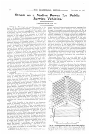
Detailed Description of Boiler.—Fig. 4 is a vertical section of the semi-flash boiler which is composed of 13 dements or conical coils of tube, involute in plan, and enclosed by a cylindrical casing. The alternate coils are moved round half a revolution in assembling, which has the effect of staggering the spirals and so breaking up the gases during their passage among the tubes. The coils are bolted to a conical steel frame which rests upon the main frame (F). Beneath F is secured a cylindrical fire-box, the upper part of which is lined with a coil of close wound tube. This forms a water-lagging to the fire-box, and, besides preserving it from injury, has the incidental advantage of warming the feed water before it enters the generator. From the upper end of the feed coil the water is transferred to the topmost coil of the generator, through which it circulates from the outer edge, rising towards the apex of the cone. The water then passes to the outer edge of the coil immediately below, and so on to the one nearest the fire, with the exception that it passes by or skips over coil No. 4 from the bottom.
The conical formation of the coils is a very important matter in providing effective means for retaining the contents of the generator in place. Thus, in the upper part ot the generator the tubes are filled with water, but as the water descends and commences to evaporate, the tubes become charged with a mixture of steam and water, in which gradually the steam preponderates. In the lowest coil there is practically no water. This is the natural arrangement of the contents of the generator when running. On closing the throttle and stopping the circulation through the generator, the steam in the lower coils would naturally rise into the upper, thus allowing the water to descend and come in contact with the hotter tubes, in this way making more steam at a time when it was not required. The conical shape of the coil prevents this by providing a trap or lock, which the author has named a " steam-ratchet." The steam in each conical element can only rise into the centre part or apex, and the water gravitates to the outer edge. There they
remain until circulation recommences on the opening of the throttle. From the apex of the lowest coil the steam passes through a thermo-governor, and thence into coil No. 4, which forms a reserve immediately behind the throttle-valve. The products of combustion are allowed to escape by a chimney (updraught) in the case of single-deck omnibuses, or by lateral openings (Li and L.2) (side draught), in the case of double-deck omnibuses. The updraught is the more natural way, giving more uniform draught, and keeping the lower part of the omnibus cooler. The employment of updraught for a double-deck omnibus may necessitate a protection or cover for the outside passengers. Such a covering is not permitted by the present police regulations, although permissible in the case of tramcars. In the author's opinion it would be far preferable if the products of combustion on both steam and petrol cars were discharged upwards. The omnibuses would be cooler and sweeter for passengers, and there would be no offensive trail to the inconvenience of pedestrians and other users of the road. The author is informed that the upward discharge is now insisted upon by the Parisian authorities. Governing Gear.—This is a most vital part of the generator combination, since upon it depends, not only the regular and efficient working, but the very existence of the boiler itself. The governing gear may be divided into lire control and water control. Fire Control.—It must be understood that the full power of the burner is in excess of the maximum demands for heat, and the fierceness of the flame is continually kept in check by the governor, in a manner analogous to the action of a steam-engine governor, which regulates the supply of steam in accordance with the variations of the load. The main principle governing the fire control is the maintenance of an equable temperature in the steam which is generated; in other words, Mc supply of heat to the generator is governed by the temperature of the steam generated. The steam is delivered from the generator in a superheated state, and from 7oo F. to Soo' F. is found to be a convenient temperature. The employment of highly superheated steam is essential for economical working.
In order to employ the temperature of steam as a governing factor, the most effective control of the fire is secured by the combined action of temperature and pressure. The temperature is the main factor when running, and the pressure when standing. The employment of pressure is really a conversion of thermal effect to meet the special circumstances of the case, and, speaking broadly, the control of the fire is due to the temperature of the generator and its contents.
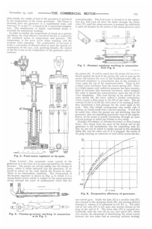
Water Control.—The automatic water control of the generator is in the form of a by-pass regulated by the steampressure. The pumps are always taking the full charge of water, which is either delivered into the generator, or allowed to return to the tank should the by-pass be open. There is no intermediate condition. The construction of the by-pass regulator is shown in Fig. 5, in which A is a spring-loaded piston which is subject to the steam-pressure acting through the water of condensation which fills the
connecting-pipe. The feed-water is forced in at the connection (C), and must all enter the boiler through the checkvalve (V), until the steam-pressure is pumped up sufficiently to open the by-pass by the action of the steam-pressure upon
the piston (A). It will be noted that the piston (A) has to 1,e forced against the load of the spring (S), and as soon as the centre rod touches the stem of the mushroom-valve (M), an increased resistance is encountered, due to the pressure of water upon the top of the mushroom-valve. There is also a slight extra resistance from the return spring (SI). There is a slight pause until sufficient pressure has been accumulated to overcome this increased resistance, when instantly the valve is opened the water-pressure upon the top of the valve disappears. This load having to be carried by the main spring (S), the latter suffers a further compression which causes a little jump in the lift of the valve. The advantage of this is to lift the valve clear of its seating (i inch), thus permitting a free passage for the water back to the tank. This very simple arrangement also avoids risk of fouling, as would result from a partial opening. It will also be noted that, when the pumps are not delivering into the generator, they are absorbing practically none of the enginepower, as the water is merely circulating through an unrestricted passage in which the friction is very small.
Detailed Description of Thermo-Governor or Fire-Control Gear.—The steam from the apex of the lowest coil of the generator is led immediately into the expanding tube (E, Fig. 6), one end of which is rigidly secured to the clamping block (B), and the other end of E is plugged, the centre of the plug carrying an extension or stud which moves the bur ner-control gear. Inside the tube (E) is a smaller tube (El), also secured to the clamping block (B), and passing directly through it, whence it is connected to coil No. 4. The other end of the tube (El) is left open and reaches almost to the plug in the end of E. The inner tube (El) is secured concentrically with the tube (E) by the wire spiral (W), which also secures the advantage of distributing the steam evenly between the two tubes and so ensuring uniform heating. The clamping block (B) is securely bolted to one side of the main frame, and the other or free end of the tube (E) is supported in a bracket also attached to the frame through which it can slide freely as its length changes, owing to variations in the temperature of the steam passing through it, It will be noted that the whole of this thermo-governor is constructed of steel.
A movement of about 5-16th inch is obtained in the free end of the tube (E) between normal temperature of the zitmosphere—say 6oF.—and the working temperature of the generator. 'I his endwise movement is translated directly to the burner-control gear (Fig. I). This form of governor is found to be quite effective for preventing an undue rise of temperature in the generator, so long as the steam within the generator is allowed to circulate; but when the circulation ceases—as on closing the throttle—the thermostat gradually loses heat by radiation, although well lagged, and in a short time would cause the burner flame to be increased. The futther heat thus supplied to the generator would have little or no effect upon the thermostat, seeing that the latter is entirely outside the fire-box. It is therefore necessary, as indicated above, to employ other means for preventing the addition of heat to the generator when the circulation of steam is stopped. Accordingly a spring-loaded piston (Fig. 7) is arranged to turn down the supply of heat as soon as the pressure within the generator exceeds normal limits.
The immediate effect of shutting-off steam to bring the car to rest is to cause an increment of pressure by the momentum of generation, which speedily brings the supplementary cylinder into action. It is found in practice that, before the omnibus has come to rest, the burner has been shut down to the minimum flame.
Conversely, when starting again the immediate effect of opening the throttle is to cause a reduction ia pressure, which is responded to by the supplementary cylinder withdrawing and allowing the fire-control to be regulated by the thermostat.
The rock-shaft (Fig. 1). situated between the thermostat and the pressure regorlater, is fitted with a double lever, which is pushed on the one side by the thermostat (Fig. 6), and on the other side by the supplementary cylinder (Fig. 7). This forms an extremely simple and convenient arrangement for the interchangeable action of the dual system of control. The rock-shaft is directly connected by a couplingrod to the burner-control, the said coupling-rod being provided with a spring dash-pot, which allows an increase in the length of the coupler in the event of a slight Overrun on the part of the governors, thus avoiding strain and deformation of the gear.
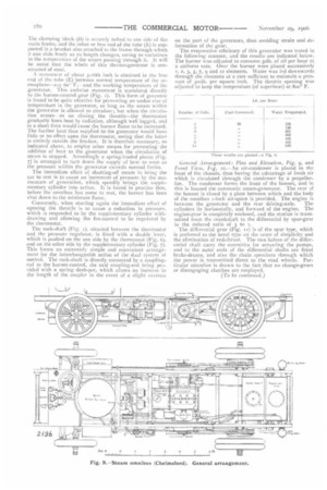
The evaporative efficiency of this generator was tested in the following manner, and the results are indicated below. The burner was adjusted to consume soIb. of oil per hour aL a uniform rate. Over the burner were placed successively r, 2, 3, 5, 7, and 12 elements. Water was fed downwards through the elements at a rate sufficient to maintain a pressure of 3oolb. per square inch. The throttle opening was adjusted to keep the temperature (of superheat) at g00° F.
General Arrangement: Plan and Elevation, Fig. 9, and Fr-ma View, Fig. io.—An air-condenser is placed in the front of the chassis, thus having the advantage of fresh air which is circulated through the condenser by a propellerfan. The condenser forms the front of the bonnet, and in this is housed the automatic steam-generator. The rear of the bonnet is closed by a plate between which and the body of the omnibus t-inch air-space is provided. The engine is
between the generator and the rear driving-axle. The cylinders lie horizontally, and forward of the engine. The engine-gear is completely enclosed, and the motion is transmitted from the crankshaft to the differential by spur-gear in the reduced ratio of 3 to 1.
The ditTerential gear (Fig. 1) is of the spur type, which is preferred to the bevel type on the score of simplicity and the elimination of end-thrust. The two halves of the differential shaft carry the eccentrics for actuating the pumps, and to the outer ends of the differential shafts are fitted brake-drums, and also the chain sprockets through which the power is transmitted direct to the road wheels. Particular attention is drawn to the fact that no change-gears or disengaging clutches are employed.