


Brakes, 4
Page 63
If you've noticed an error in this article please click here to report it so we can fix it.
IN THE last article it was said that air braking components could be divided into four groups (1) Compression and Storage, (2) Control, (3) Actuation and (4) Indication, and it is proposed to deal with each of these in turn.
Air compressors are sometimes driven off the engine, sometimes independently. In some designs the crankshaft of the air compressor is used to drive other auxiliaries, for example, the fuel injection pump. The compressor illustrated in Figure 1, which is of the type fitted to the Leyland Roadtrain, is mounted on the engine timing case and is gear driven. This illustration is re-produced by permission of Leyland Vehicles.
Compressors may have twin cylinders, as the one illustrated in Figure 1 or a single cylinder.
They may be air or water cooled and their lubrication system may be self-contained, although it is more usually connected with that of the engine.
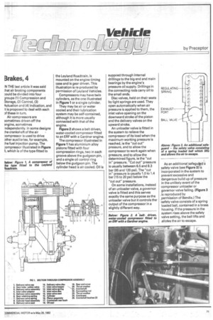
Figure 2 shows a belt driven, water-cooled compressor fitted to an ERF with a Gardner engine.
The compressor illustrated in Figure 1 has aluminium alloy pistons fitted with four compression rings, two in each groove above the gudgeon pin, and a single oil control ring below the gudgeon pin. The cylinder head is air cooled. Oil is supplied through internal drillings to the big end and main bearings by the engine's pressure oil supply. Drillings in the connecting rods carry oil to the small ends.
Disc valves, held on their seats by light springs are used. They open automatically when air pressure is applied to them, the inlet valve opening on the downward stroke of the piston and the delivery valves on the upward stroke.
An unloader valve is fitted in the system to relieve the compressor of its load when the maximum working pressure is reached, ie the "cut out" pressure, and to allow the compressor to work again when 'pressure, and to allow the determined figure, ie the "cut in" pressure. "Cut out" pressure is usually between 6.5 and 8.3 bar (95 and 120 psi). The "cut in" pressure is usually 1.0 to 1.4 bar (15 to 20 psi) below the "cut out" pressure.
On some installations, instead of an unloader valve, a governor valve is fitted and this serves exactly the same purpose as the unloader valve but it controls the output of the compressor in a slightly different way.
As an additional_safegutyd a safety valve (see Figure 3) is incorporated in the system to prevent excessive and dangerous build up of pressure in the unlikely event of the compressor unloader or governor valve failing. (Figure 3 , is reproduced by ipermission of Bendix.) The 'safety valve consists of a spring loaded ball, contained in a brass housing. If the pressure in the system rises above the safety valve setting, the ball lifts and allocvs the air to escape.