


Unified Control for Two Injection Pumps
Page 36
If you've noticed an error in this article please click here to report it so we can fix it.
AN intimation that Leyland Motors, Ltd., Ham Works, Kingston-onThames, is interested in V-type engines, or units with opposed cylinders, comas in patent No. 544,020, which describes a scheme• for ensuring identical control for two separate injection pumps. The patent also bears the name S. Markland, Hough Lane, Leyland, Lancs.
With any engine it is desirable to keep the injection pipe lines as short as possible, and in the case of an engine in which two banks of cylinders are widely separated it may be impracticable to pipe them from a single pump. In the present patent, two pumps are envisaged, one to each block of cylinders, and the control gear must therefore ensure unanimity of output.
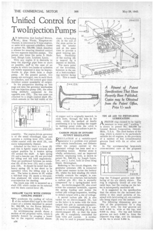
In the perspective drawing on this page are seen the governor mechanism and one injection pump (10), the other being similarly connected .to the opposite arm (15). The two arms are attached to a single control shaft (8), which extends to the full width of the assembly. The engine-driven governor is of the usual centrifugal type and operates a rocking lever (11), which, whilst coaxial with the shaft (8), can move independently thereof.
Attached to the, shaft is a lever (6) and this is lightly urged towards fulloutput position by a torsion spring (7) around the shaft. A light spring (1) and a heavier one (2) are provided for idling and full load respectively. They. are positioned between an extension (5) of the lever (11) and a crankarm (14). It should be noted that the heavy spring (2) is too short to be operative when the idling stop is in use. The latter is shown at 13, whilst a full-load stop (3) meets a two-position abutment (4) which can permit over-injection for starting.
The crank arm (14) is mounted on a shaft (12) which carries on its external end the main control lever (9).
HOLLOW VALVE WITH COPPER COOLING INSERT
17accelerate the cooling of valves f the sodium-filled type is the chief object of a scheme described in patent No. 544,128, by the Eaton Manufacturing Co., Cleveland, Ohio, U.S.A.
An accompanying sketch shows a section of the proposed valve, which is initially formed by swaging a bored bar to the required external dimen
sins. A hard plug (3) in the end of the stem serves to seal the interior and at the same time to provide a good wearing surface. Durability of the seating (2) is assured by a deposit of Stellite, The main point of the invention, however, is the use of a heat-conducting interior facing (1). This is made
of copper and is originally insertcd, in stick form, through the hole in the stem, whilst the method of finally positioning it is by heating the copper to melting point while the valve is spun. Afterwards the sodium is put in.
CARBON PILES IN DYNAMO OUTPUT REGULATOR
REGULA TI ON of a variable-speed generator is a problem ever present with vehicle installations, and hitherto either the output current or the generated voltage has been used as a
controlling means. Neither alone is wholly satisfactory, and an improved method, employing both, is shown in patent No. 544,101, by Joseph Lucas, Ltd., and J. Laird, both of Great King Street, Birmingham.
Referring to the circuit diagram, the generator armature (10) is connected in the usual manner across the battery (6); whilst the field winding (1) which actually controls the output, is connected across the armature, but includes a carbon pile (9) ; this is normally compressed by a spring-loaded lever (2). An electro-magnet (8), also wired across the armature terminals, opposes the spring loading and makes the carbon pile voltage-responsive, tending to reduce output with a rise of voltage.
A second carbon pile (4) is also varied by an electro-magnet (5), but as the latter is in series with the main
output this pile current-responsive. The circuit containing pile 4 is connected to a second winding (7) on the electro-magnet (8), so that the main pile (9) is completely controlled for
both volts and current. A rectifier (3) may be used to prevent hunting. TIN AS AID TO PISTON-RING LUBRICATION
APISTON ring claimed to be highly resistant to wear and " scuffing " is shown in patent No. 543,936 by General Motors Corporation, Detroit, Mich., U.S.A. The chief feature of the ring, which is stated to be particularly suitable for oil engines, is the provision of a number of fine circumferential grooves lined with tin or other soft metal.
• In the accompanying large-scale cross-sectional view of the proposed
ring the V-shaped grooves and their facing of tin are clearly shown, The ring is originally tinned all over the outer face, but the coating on the latter is subsequently machined off.
It is suggested in the specification that the reason for the increased durability is that small particles of tin, mixed with lubricating oil, are continually being wiped over the surface.
The following dimensions give an idea of the proportions: In a ring 0.125 in. wide, the fourgrooves are each 0.010 in. wide at the top, and 0.015 in. deep. The top and bottom grooves are each 0.020 in. from the adjacent ring edge, and the thickness of the tin is about 0.004 in.