


A Novel Engine Mounting
Page 60
If you've noticed an error in this article please click here to report it so we can fix it.
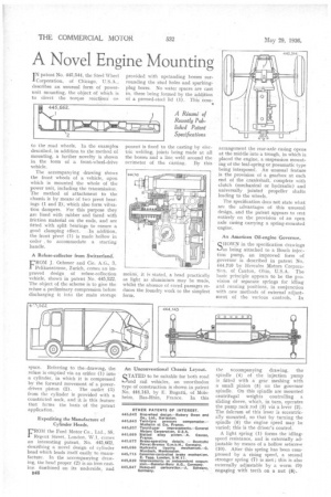
I N patent No. 446,544, the Steel Wheel Corporation, of Chicago, U.S.A., describes an unusual form of powerunit mounting, the object of which is to direct the torque reactions" or to the road wheels. In the example described, in addition to the method of mounting, a further novelty is shown in. the form of a front-wheel-drive vehicle.
The accompanying drawing shows the front wheels of a vehicle, upon which is mounted the whole of the power unit, including the transmission. The method of attachment to the chassis is by means of two pivot hearings (1 and 2); which also form vibration dampers. For this purpose they are lined with rubber and faced with friction material on the ends, and arc fitted with split hearings to ensure a good clamping effect. In addition, the front pivot (1) is made hollow in order to accommodate a starting handle,
A Refuse-collector from Switzerland. FROM J. Ochsner and Cie. A.G., 3, Pelikanstra,sse, Zurich, comes an improved design of refuse-collection vehicle, shown in patent No. 445,522. The object of the scheme is to give the refuse a preliminary compression before discharging it into the main storage
space. Referring to the ,drawing, the refuse is emptied via an orifice (1) into a cylinder, in which it is compressed by the forward movement of a power driven piston (2). The outlet (2) from the cylinder is provided with a constricted neck, and it is this feature that forms the basis of the patent application.
Expediting the Manufacture of Cylinder Heads.
FROM the Ford Motor Co., Ltd., 88, Regent Street, London, W.1, comes an interesting patent, No. 445,6M, describing a novel design of cylinder head which lends itself easily to manufacture. In the accompanying drawing, the head proper (2) is an iron casting. Machined on its underside, and
846 provided with upstanding bosses surrounding the stud holes and sparking.: plug bores. No water spaces are caSt in, these being formed by the addition of a pressed-steel lid (1). This corn ponent is fixed to the casting by electric welding, joints being made at all the bosses and a line weld around the Perimeter of the casting. By this means, it is stated, a head practically as light as aluminium may be made, whilst the absence of cored passages reduces the foundry work to the simplest form.
An Unconventional Chassis Layout.
STATED to be suitable for both road and rail vehicles, an unorthodox type of construction is shown in patent No. 444,143, by E. Bugatti, of Moleheim, Bas-Rhin, France. In this
arrangement the rear-axle casing opens at the middle into a trough, in which is placed the engine, a suspension mounting of the leaf-spring or pneumatic type being interposed. An unusual feature is the provision of a gearbox at each end of the crankshaft, complete with clutch (mechanical or hydraulic) and universally jointed propeller shafts leading to the wheels.
The specification does not state what are the advantages of this unusual design, and the patent appears to rest entirely on the provision of an open axle casing carrying a spring-mounted engine.
An American Oil-engine Governor.
SIIOWN. in the specification drawings as being attached to a Bosch injection pump, an improved form of governor is described in patent No. 444,710 by Hercules Motors Corporation, of Canton, Ohio, U.S.A. The basic principle appears to be the provision of separate springs for idling and running positions, in conjunction with new methods of external adjustment of the various controls. In
the accompanying drawing, the spindle (4) of the injection pump is fitted with a gear meshing with a small pinion (5) on the governor spindle. On this spindle are mounted centrifugal weights controlling a sliding sleeve, which, in turn, operates the pump rack rod (3) via a lever (2). The fulcrum of this lever is eccentrically mounted, so that by turning the spindle (6) the engine speed may be varied; this is the driver's control.
A light spring (1) forms the idlingspeed resistance, and is externally adjustable by means of a hollow setscrew (10). After this spring has been compressed by a rising speed, a second stronger spring (7) is met ; this is also externally adjustable by a worm (9) engaging with teeth on a nut (8).