


A COMBINED CONE AND HYDRAULIC CLUTCH.
Page 62
If you've noticed an error in this article please click here to report it so we can fix it.
A Résumé of Recently Published Patent Specifications.
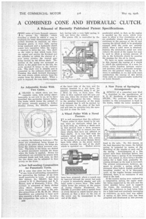
THE name of Louis Renault appears in patent No. 282,018, which describes .a clutch in which a cone is employed for total disengagement, when perfect freedom is required, as when changing gears, a very light spring being employed and a hydraulic clutch comes' into operation when the engine is required to drive the car. The shaft on the right is that which leads from the engine and carries the flywheel and the spindles on which the pistons of a gear pump revolve, the central gear being carried by the driven shaft The pinions of the pump are arranged as shown in the ,small view on the left, the ports marked E being on the delivery side. The shaft (A) is slidable and is connected to the ordinary clutch pedal. Pressing this shaft forward disengages the cone clutch, which entirely frees the engine from the driven shaft. When• a gear is engaged, the cone clutch engages, A ;BRAKE in which there, are two expander cams, both acting simultaneously, is not new to AS, BAC re!: have described this particular feature before. The brake which forms the subject of the patent recently granted to Arthur Stanley. Picton, No. 288,675, appears to contain tbe following features :—The shoes are articulated, being hinged together at the point shown, the hinge pin being the fulcrum which prevents rotation. The holes in the hinge are slotted to permit movement towards the drum when the brake is applied. Means for adjustment are provided by screws -with enlarged heads and lock nuts, so that the two shoes can be adjusted to bear evenly on the drum.
A New Self-sealing Composition for Pneumatic Tyres. • IT is some time since we have heard
of any form of self-sealing composition for preventing the leakage of air from small' punctures in tyres. A patent on this subject, No. 288,917, has been granted to B. G. Harrington and R. S. Mason, both' of Kentucky, U.S.A. • The mixture is composed of finely divided silica (flint), alumina (clay), soapstone (magnesia) and mica in the relative proportions of 40, 40, 10, 10. These ingredients are subjected to heat until they resemble a flock or down. In using the composition the valve is taken out 11.44 of the inner tube of the tyre and the mixture inserted in a dry form, the quantity recoinmended being 2 oz. for a 30-in. by 3-in. or 3i-in. tyre. The valve is then replaced and the tyre put int& use, when the mixture will distribute itself throughout the tube. Owing to •the peculiar formation of the mass it is claimed that it will be carried by leak currents to the place of the leak end will jam its particles into the opening, and so close the leak. •
A Wheel Puller With a Novel Feature.
IT is well recognized that the ordinary
wheel puller is often found to be useless when an obstinate wheel has to be dealt with, as, without a shock such as that derived from a blow; pressure alone will often fail to remove any but those wheels that have not adhered to their shafts. It is true that with the ordinary wheel puller one can hit the narrow end of the screw, but, owing to the nature of the screw thread, blows have little effect, as the screw cannot advance towards the end of the shaft which is operated on. Hollow screws have been proposed, where a punch can be inserted through the screw, but such a punch is necessarily slender and will bend under a severe blow. The puller which forms the subject of the patent of Irving Charles Woodward, No. 279,865, is provided with a special form of screw thread in which lateral play is allowed, so that a blow on the end of the screw can be transmitted to the end of the shaft. accelerator pedal, so that, as the engine is speeded up, the ports, which were open to allow a free circulation of oil, are gradually closed, thus setting up a resistance to the passage of the oil and causing the driven shaft to be gradually engaged until the ports are entirely closed, when a solid drive is obtained. Raising the accelerator pedal not only reduces the speed of the engine but may be used to allow a certain amount of slip in the hydraulic clutch by opening the passage for the oil to travel.
We have on many occasions foretold in this journal the coming of a clutch in which the combination of a cone for giving entire freedom between engine and gearbox, with a hydraulic arrangement for the gradual taking up of the drive is embodied, BO We hail with some satisfaction the coming of this device from such an unquestionable authority as Louis Renault.
A New Form of Springing Arrangement. A SPRING of a somewhat new kind is described in the specification of K. B. W. Sandberg, of Stockholm, No. 277,707. We presume .thot the top member in this arrangement is fixed to the frame, whilst the lower member is fixed to the axle. By this means, as the load depresses the frame, the helical spring is extended by means of the flattening of the toggles at each end of the spring. • Arrangements of a like nature have been described before, but in most cases a spring of an inconstant kind was aimed at, there being a flexible spring for a light load, gradually becoming stronger as the load is increased. The present arrangement, however, appears to provide a spring which is strongest when lightly loaded, gradually becoming weaker as it is depressed, until, as the toggles become completely flattened, there is no resistance of any kind to the load.
If the tension spring were replaced by a compression spring, the upper member being supported by the axle and the lower member being used to support the frame, the conditions would be ideal, the resistance to load being light for a light load and gradually increasing in resistance as more load was added. A spring of this latter type has been proposed and illustrated in this journal.