


HINTS ON MAINTENANCE.
Page 30
If you've noticed an error in this article please click here to report it so we can fix it.
How to Get the Best Out of a Vehicle, to Secure Reliability and to Avoid Trouble.
379.—Adjusting Tappets on 3.13,4 Type Tylor Engines.
The body is of cast iron with a slotted portion at the bottoi which retains the roller, and any considerable force applied to the nuts causes a shearing action to take place at the points (a) and (b), with the result that the tappet may break at these points and the roller will then fall into the crankcase. Therefore, _when making adjustment, use a very short spanner and apply only sufficient force to ensure that the nut will not loosen.
Incidentally, we would point out that the adjustment of these tappets is seldom required.
380.—Dismint1ing the Garner Clutch.
The clutch of the 2-tori G type Garner chassis is of the multiple disc type, the discs being enclosed in an outer drum bolted to the flywheel. In order to examine or replace them, it is neeeseary to remove the retaining bolts. On examination it will be found that the nuts only are accessible, the heads or the bolts being behind the flywheel and hidden from view by the engine base, -which extends and encircles the flywheel so far as its outer edge.
To render the bolts accessible for this and future occasions, it is advisable to cut a neat hole, large enough to admit a box spanner, in the face of the base exteneion at the back of the flywheel and on the near side only of the engine. The retaining bolts can now be removed one by one by rotating the flywheel after each is extracted.
The tutting of the hole does not weaken the base in any way, and when the job is finished. the hole may be covered by a small plate of sheet metal shaped to
provide an oil-tight joint and drilled for in.. setscrews, for which the base must also be drilled and tapped.
381.—The Care of Leather Universal Joints.
A certain number of vehicles is fitted with universal joints of the leather disc type, and sometimes cornolaints are made that these joints often give out. This not Only means a delay in transport work, hut may involve expense for replacements of the leather discs themselves and the possibility of having to repair further damage caused by the front end of the propeller shaft dropping to the ground.
It has been found that trouble of this nature can B44
be avoided by making ireqeent inspections of the joints. One common cause of undue wear on the joints is movement of the rear axle in relation to the chassis, caused by fractures of the centre pins passing through the rear springs, and aleo the loosening of the holding-down bolts for these springs.
382:—A Baffle for Loose Jets.
Cases have occurred in Tylor engines fitted with Claudel-Hobson carburetters of the jet tops becoming loose and being sucked up the inlet pipe into the cylinders, where they may lodge under the valves and cause these to barn, through being held off their seatines, or the tope may drop right into the cylinders. Being small, they are not likely to cause breakages, but the loss may not be noticed until the excessive petrol consumption makes itself apparent.
To prevent this trouble occurring, a strong gauze -should be included in the joint just above the carburetter. If this be done, a jet top which has .become detached will fall down into the throttle
.383.—Keeping the Brakes Efficient.
On a motor vehicle efficient braking power is almost as essential as engine power, and the following advice may be-found helpful in maintaining this efficiency.
1. Whenever possible use the engine as the first braking medium, afterwards applying either one or both brakes as required. This, of course, does not apply to emergency stops.
2. When descending a hill check the speed by means of the engine used in conjunction with the brakes. To allow these to cool they should be used alternately for a few seconds ealh, releasing one as the other is applied.
• 3. Remove any traces of oil from the surfaces of the brake drums and shoes and, in the case of brakes of the metal-to-metal type, periodically remove the metallic dust which results from wear and which is apt to have an abrasive effect on the wheel bearings. • 4. Carefully and frequently lubricate all the actuating levers, the knuckle joints and the ratchet and pawl of the hand-brake lever.
5. Make certain that the floorboards of the cab do not impede the travel of the pedal.
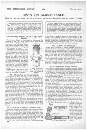
6. Examine the knuckle joints and ensure that no fouling occurs between the levers and the fork ends, as is el-town in the illustration.
7. In those instances where the brake has two points for adjustment—one for either road wheel —be careful to equaliae the pressure on the drums.
A common fault with brake connections is fouling of the forks as shown.
8. Carefully clean and oil the screwed portions of all brake rods. This will render their adjustment easier.