


New Types of
Page 64
If you've noticed an error in this article please click here to report it so we can fix it.
Worm Gearing
A Mstane of Recently Published Patent Specifications
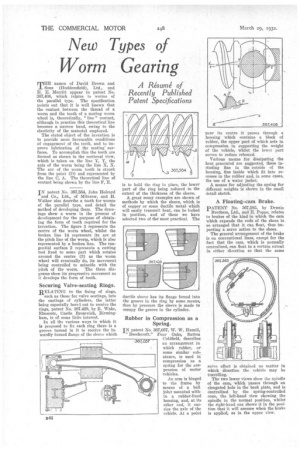
MHB names of David Brown and Sons (Huddersfield), Ltd., and EL E. Merritt appear in patent No. 367,408, which relates to worms of the parallel type. The specification points out that it is well known that the contact between the thread of a worm and the tooth of a mating worm wheel is, theoretically, " line " contact, although in practice this theoretical line becomes a narrow band, owing to the elasticity of the material employed.
The stated object of the invention is to provide more favourable conditions of engagement of the teeth, and to improve lubrication of the mating' surfaces. To accomplish this the teeth are formed as shown in the sectional view, which is taken on the line Y, Y, the axis of the worm being the line X, X. The arc of the worm tooth is struck from the point (D) and represented by the line C, A. The theoretical line of contact being shown by the line F, E.
IN patent No. 367,564, John Holroyd and Co., Ltd., of Milnrow, and EC. Walker also describe a tooth for worms of the parallel type, and detail the method of developing them. The drawings show a worm in the process of development for the purpose of obtaining the form of tooth required for the Invention. The figure 3 represents the centre of the worm wheel, whilst the broken line 14 represents its arc at the pitch line of the worm, which is also represented by a broken line. The tangential surface 2 represents a cutting tool fixed to some part which rotates around the centre (3) as the worm wheel will eventually do, its movement being controlled to coincide with the
pitch of the worm. The three diagrams show its progressive movement as it develops the form of tooth.
Securing Valve-seating Rings.
RELATING to the fixing of rings, such as those for valve seatings, into the castings of cylinders, the latter being especially borei out to receive the rings, patent No. 367,429, by It. Wake, Elmscote, Castle Bromwich, Birmingham, is of some little interest.
In all the various ways in which it is proposed to fix each ring there is a groove turned in it to receive the inwardly turned flange of the sleeve which. is to hold the ring in place, the lower part of the ring being reduced to the extent of the thickness of the sleeve.
A great many examples are shown of methods by which the sleeve, which is of copper or some ductile metalwhich will easily transmit heat, can be locked in position, and of these we have selected two of the most practical. The ductile sleeve has its flange forced into the groove in the ring by some means, then by pressure the sleeve is made to occupy the groove in the cylinder.
Rubber in Compression as a Spring.
IN patent No. 367,057, W. W. Hamill, " Beechcroft." Four Oaks, Sutton Coldfield, describes an arrangement in which rubber, or some similar substance, is used in compression as a spring for the suspension of motor vehicles.
An arm is hinged to the frame by means of a ball joint mounted within a rubber-lined housing, and, at its other end, it carries the axle of the vehicle. At a point
near its centre it passes through a housing which contains a block of rubber, the upper part of which acts in compression in supporting the weight of the vehicle, whilst the lower part serves to reduce rebound.
Various means for dissipating the heat generated are suggested, these including fins in the outside of the housing, fins inside which fit into recesses in the rubber and, in some cases, the use of a water jacket.
A. means for adjusting the spring for different weights is shown in the small detail sketch.
A Floating-cam Brake.
PATENT No. 367,583, by Dennis Brothers, Ltd., and E. Poppe, relates to brakes of the kind in which the cam which expands the ends of the shoes is. so arranged that it can float, thus imparting a servo action to the shoes.
The general arrangement of the brake is on conventional lines, except for the fact that the cam, which is normally centralized, can float to a certain extent in either direction so that the same servo effect is obtained no matter in which direction the vehicle may be travelling.
The two lower views show the spindle of the cam, which passes through an elongated hole in the back plate, and is centralized by the spring-controlled cone, the left-hand view showing the spindle in the normal position, whilst the right-hand one shows it in the position that it will assume when the brake is applied, as in the upper view.