


Technical Features of the
Page 62
Page 63
If you've noticed an error in this article please click here to report it so we can fix it.
BOTTOM FRAMEWORK
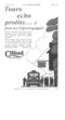
Our Expert Describes the Construction of the Bottom Framework of a Passenger Vehicle and Explains How Certain Difficulties May be Overcome
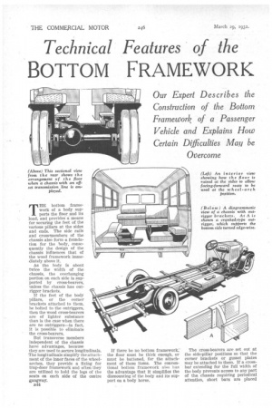
THE bottom framework of a body supports the floor and its load, and provides a means for securing the feet of the various pillars at the sides and ends. The side rails and cross.members of the chassis also form a foundation for the body, consequently the design of the chassis influences that of the wood framework immediately above it.
As the body is about twice the width of the chassis, the overhanging portion on each side is supported by cross-bearers, unless the chassis has outrigger brackets.
If the feet of the body pillars, or the corner brackets attached to them, be bolted to the outriggers, then the wood cross-bearers are of lighter substance than is the ease when there are no outriggers—in fact, it is possible to eliminate the cross-bearers.
But transverse members independent of the chassis have advantages, because they are used to secure longitudinaIs. The longitudinals simplify the attachment of the inner faces of the wheelarches, they provide a fixing for trap-door framework and often they are utilized to hold the legs of the seats on each side of the centre gangway.
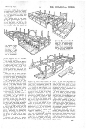
B•14 If there be no bottom framework, the floor must be thick enough, or must be battened, for the attachment of these items. The conventional bottom framework also has the advantage that it simplifies the dismounting of the body and its support on a body horse. The cross-bearers are set out at the side-pillar positions so that the corner brackets or gusset plates may be attached to them. If a crossbar extending for the full width of the body prevents access to any part of the chassis requiring periodical attention, short bars are placed between the outside of the body and the longitudinals above the chassis. A centre bar is framed-in as closely as possible to these two outer bars and the whole is reinforced with corner plates.
The bottom side is the outer lengthwise member of the frame at the floor level. Formerly, the hot tom side held the feet of the pillars, but now that the standards are extended below the top of the
chassis another rail is lapped in below for this purpose.
The bottom side forms a bearing for the outside panels and supports the edge of the floor, unless there be a special floor fillet. It is interrupted at all wheel-arch and entrance positions, but it is continued below a rear emergency exit when the door opens at the floor When the bus or coach has the conventional variety of steering, the bottom side curves inwards towards the dash in order to conform with the shape of the scuttle panelling.
The floorboards may be laid lengthwise if the transverse members of the bottom frame be closely spaced. The usual practice, however, is to place the boards crosswise. Then each board has a bearing on tile two bottom sides and on a pair of Iongitudinals having centres about 2 ft. 1 in. apart.
The outrigger brackets form a continuation of the top surface of the chassis. If the bracket he cranked downwards so as to resemble a step stay, the bottom side may be stood up edgewise on the outer end of these cranked brackets and thus form a bearing for the ends of the cross-members.
With an outrigger bracket having a 6-in, crank, the bottom side has the same depth and is about thick. It thus acts as a useful wood girder. Moreover, this girder may be used as a fixing for the feet of the pillars and there will be space for a pair of bolts to secure each pillar.
Although the floor is usually placed as close as possible to the
chassis by using cross-bearers of minimum thickness or by eliminating them, there are occasions when it is an advantage to raise a portion of it.
A wheel-arch may project 1 ft. 2 ins, above the floor, inwhich case it is too high for a crosswise seat to be placed above it. But if the floor under the seats be raised 7 ins., 'The wheel-arch obstruction is reduced sufficiently to allow cross-wise seats to be adopted throughout. The centre aisle is at the normal level and a step has to be negotiated in order to enter the cross-gangway.
This style of floor should be designed in conjunction with a headroom an inch or two in excess of the minimum of 5 ft. 10 ins, stipulated under the regulations, in order to give required ease of ingress and egress for passengers.
With a minimum height of floor there may be insufficient clearance above the differential casing. 'A compromise is sometimes made by leaving a circular space in the floor and covering it with a dome-shaped plate. In this way one gains not only the thickness of the floor but the height of the dome above it. Care must be taken not to give to the dome too small a radius or it may prove dangerous, in that passengers too easily stumble over it.
A better plan is for the transmission to be offset, so that any cover plate required may be placed on the near side and concealed as much as possible-under the longitudinal seat.
The bottom framework of a double-decker is similar to that of a single-decker from the front bulkhead to the pillar immediately behind the wheel-arch, but beyond the rear bulkhead the side members of the chassis are cranked downwards to receive the platform.
Sometimes these tail ends are splayed outwards towards the rear, in order to reduce the side overhang of the platform, where heavy strains are often encountered. The extra width of the chassis at the rear may also be utilized to accommodate the spare wheel.