 1
1 2
2 3
3 4
4 5
5 6
6 7
7 8
8 9
9 10
10 11
11 12
12 13
13 14
14 15
15 16
16 17
17 18
18 19
19 20
20 21
21 22
22 23
23 24
24 25
25 26
26 27
27 28
28 29
29 30
30 31
31 32
32 33
33 34
34 35
35 36
36 37
37 38
38 39
39 40
40 41
41 42
42 43
43 44
44 45
45 46
46 47
47 48
48 49
49 50
50 51
51 52
52 53
53 54
54 55
55 56
56 57
57 58
58 59
59 60
60 61
61 62
62 63
63 64
64 65
65 66
66 67
67 68
68 69
69 70
70 71
71 72
72 73
73 74
74 75
75 76
76 77
77 78
78 79
79 80
80 81
81 82
82 83
83 84
84 85
85 86
86 87
87 88
88 89
89 90
90 91
91 92
92 93
93 94
94 95
95 96
96 97
97 98
98 99
99 100
100 101
101 102
102 103
103 104
104 105
105 106
106 107
107 108
108 109
109 110
110 111
111 112
112 113
113 114
114 115
115 116
116 117
117 118
118 119
119 120
120 121
121 122
122 123
123 124
124 125
125 126
126 127
127 128
128 129
129 130
130 131
131 132
132 133
133 134
134 135
135 136
136 137
137 138
138 139
139 140
140 141
141 142
142 143
143 144
144 145
145 146
146 147
147 148
148 WEIGHING Ul E EV DENCE
Page 56
Page 57
Page 58
Page 59

If you've noticed an error in this article please click here to report it so we can fix it.
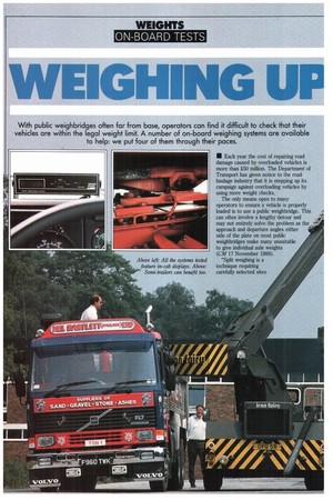
With public weighbridges often far from base, operators can find it difficult to check that their vehicles are within the legal weight limit. A number of on-board weighing systems are available to help: we put four of them through their paces.
• Each year the cost of repairing road damage caused by overloaded vehicles is more than .250 million. The Department of Transport has given notice to the road haulage industry that it is stepping up its campaign against overloading vehicles by using more weight checks.
The only means open to many operators to ensure a vehicle is properly loaded is to use a public weighbridge. This can often involve a lengthy detour and may not entirely solve the problem as the approach and departure angles either side of the plate on most public weighbridges make many unsuitable to give individual axle weights (CM 17 November 1988).
"Split weighing is a technique requiring carefully selected sites
I and some skill," says the DTI's own Trading Standards Department.
Faced with a situation where prosecution for overweight offenders is likely to become more prevalent, more operators are considering fitting some type of axle weight indicator or on-boardweighing equipment. However, though the vast majority have yet to be convinced that the equipment is sufficiently reliable to ensure that the sometimes considerable initial investment will give a payback in terms of increased revenue through maximising payloads.
These doubts are not unfounded as past xperiences have not given rise to onfidence and a recent report for some on-board weighers by the Transport and Road Research Laboratory concluded that reliability was not consistent. That was ur years ago, and the situation ought to have improved since then.
In an effort to find out we asked manufacturers to provide us with a
suitably equipped vehicle for assessment. Three companies accepted the invitation: Red Forge of Redditch supplied a 4x2 Renault G16, Maywood Onboard of Basingstoke provided a 6x4 Volvo Fl? and PM Electronics of
Bradford supplied two vehicles, a 6><4 Volvo and a 6x2+3 Volvo F10 articulated combination.
All four vehicles had been equipped for some time and were only withdrawn from service for the day of the test. At the outset, we provided an opportunity for each of the systems to be calibrated against an electronic weighbridge at test site. Each vehicle was loaded wi about 75% of its payload with test weights of known values, loaned by Leyland Daf.
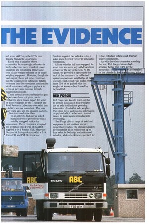
RED FORGE
Red Forge was keen to point out that its system is not an on-board weigher but an axle load indicator providing information of individual axle weights. The other three systems give information on payload which can be used, in most cases, to guard against individual axle overloading.
Red Forge offers a range of axle load equipment to suit multileaf and airsuspended vehicles. The standard Axalert air suspension kit is available for up to four axles for both rigid and articulated vehicles, while other kits are specified for refuse collection vehicles and drawbar trailer combinations.
As with the other companies attending the test, Red Forge claims a high accuracy better than ± r the electronics on the chassis do ifia the systems. For the axle load indicator systems supplied, a sensor unit is mounted on the chassis, linked to the axle by a rod so that the system depends upon spring movement being consistent for a given load. Technical director John Brown says that the axle load equipment is not recommended for use with monoleaf suspension, as movement is insufficient to give a satisfactory level of accuracy. But rubber suspensions give very consistent readings better than with multileaf suspensions which are said to give an accuracy of better than ±5% at the point of overload.
In the cab a display unit uses a light column to show increasing load above 60% of the axles' plated weight. This is backed up by an audible warning at the point of overload. The test vehicle incorporates an optional digital display for each axle calibrated in tonnes to one decimal point.
The test involved recording front axle. rear axle and total weight readings from the display unit as the vehicle was placed: facing up and facing down a 1.5° gradient; facing each way across a 2.50 slope, and, after running over a heavily-ribbed section of the track at slow speed accompanied by 5km of normal running, a final check weigh once more at the point of calibration on the level weighing platform.
In practice, we found that even on this test track there were very few sites which we considered to be level and suspect that in a working environment it would be even more difficult to find a level piece of ground.
From the first set of figures it can be seen that while the indicated weight of the rear axle remained similar, there was a wide variation between readings for the front axle at the different locations. And due to the coarseness of the readout, individual axle weights do not add up to the total.
The start and finish figures show a variance of 0.7 tonnes on the front axle, or 14% of the original indicated weight, while at the rear the variance is just 1%. On total weights there is a difference of 5.6%. As this is outside the claimed accuracy, Red Forge asked to recalibrate. At the end of a re-run the calibration figure remained much closer to the final reading, but still exceeded the claimed accuracy on the slight gradients, and again the individual axle weights disagreed with the total.
MAYWOOD ONBOARD
Maywood Onboards' Payload and more sophisticated Loadmaster systems, .designed and produced in the UK, costs in the region of £3,000 to £4,000 and includes all of the brackets used to attach the loadcells to the chassis. In the case of the payload system supplied, it includes the tipping ram pivot and the rear body hinge bracket, as it is important that the mountings provide a rigid base for the loadcells. To re-programme the digital indicator access is gained using a removable electronic key. This ensures that there is no unauthorised interference with the display. After a short settling-in period it should not need recafibrating.
To take a reading the body is first raised just clear of the chassis. Once the display has been calibrated, the body must be set at the same height for any subsequent readings. Although the payload system does not give a direct indication of individual axle weights, it is a simple matter to deduct the unladen axle weight values to determine a limit of imposed loads on front and rear of the body to prevent overloading.
While the recorded values show a small variance from the level readings and move in a contrary direction to that expected for a given gradient, they remain within the tolerance quoted, even without allowing for load transfer. Total payload display was consistent throughout the test.
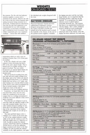
PM ELECTRONICS
PM Electronics provided us with a more basic payload system. It showed an initial weight which differed by 0.04 tonnes from the weighbridge's and the manufacturer decided no adjustment was needed. Weighing is similar to that of the other 6x 2 tipper, but to give any indication of axle weights the driver would have to rely on an evenly-distributed load. The single reading of total payload varied by 0.1 tonne.
Conversely, the most sophisticated system for test was also supplied by PM Electronics. The trial& Volvo F10 tractive unit, and triaxle trailer is fitted with eight load cells, two incorporated in the fifth wheel mount and a pair for each axle. The display gives a readout of imposed load on the kingpin, on the bogie and the total payload.
As with the 6x4 tipper, it is possible to determine a payload value which will prevent individual axle overloading. The system supplied weight values to the nearest 50kg and rounds up or down to the nearest 0.1 tonne on the display_ This sometimes results in a 0.1-tonne variance in the combined king pin and bogie values to arise with the total indicated weight. Overall, the values displayed remained very stable allowing for load transfer, and correlated well with the total weight.
Weights recorded on the gradient due to the effect of load transfer are not necessarily incorrect, but they are, in most cases, at variance with the values measured on level ground, and so emphasise the importance of ensuring that the vehicle is level. All of the systems assessed by CM operated within the tolerances claimed by the manufacturer.
Ideally, any system installed in a vehicle should be protected against unauthorised adjustment. The system should also be fitted in such a manner that it will work reliably in the adverse environment in which the vehicle is expected to operate.
After only one day's testing we cannot, of course, comment on the long-term reliability of such systems. But there is no doubt that some hauliers would find the reassurance that a vehicle was operating within legal limits sufficient incentive to try out one of the on-board systems currently on the market.
Ci by Bill Brock