


Oil Engine With An •
Page 36
If you've noticed an error in this article please click here to report it so we can fix it.
Extra Scavenge Stroke
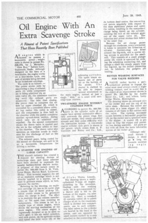
AN engine which is claimed to possess a favourable power weight ratio is shown in patent No. 568,375, by J. Macaulay, " Glen Roy," Salters Lane,
• Tamworth, Staffs. Although designed on the lines of a two-stroke, the engine works on a four-stroke cycle, one pair of strokes being devoted to an in-and-out scavenge.
The cycle is as follows .— The power stroke ends by uncovering a ring of exhaust ports (1) while compressed air is being admitted via an inlet valve (2), the admission continuing until the exhaust ports are re-covered. The inlet then closing, the piston rises to compress the air into an apper chambet (3), which is controlled by a concentric .sleeve valve. At top centre this valve is closed, and the compression is thus held in the chamber while -the piston completes another up-and-down motion, during which only air is admitted and expelled. On the second compression stroke the Sleeve valve is opened and . the air in the cylinder added to that in the chamber. The sleeve valve also uncovers an injection nozzle in readiness for the discharge of fuel at the correct moment.
The exhaust gases, being cooled by the second air discharge, are said to be at a favourable temperature for driving a turbine.
A STARTER FOR ENGINES OF LARGE CAPACITY
THPaircraft industry has created a demand for starting devices of extra-large sizes, and many schemes have beem devised to supersede the usually battery-driven electric motor. A proposal of this nature comes in patent No. 568,685 from S. M. Viale, Lynx House, Burton Road, Littleover, Derby. This inventor suggests the use of an explosive cartridge which is not directly applied to a starter, but is used to generate steam which, in turn, . operates the starter.
Referring to the drawing, an explosive cartridge (1) has in its outlet pipe a simple type of water pick-up (2), which causes steam to be generated when the charge is fired. The effect is to multiply the gas volume considerably, at the same time lowering its • temperature. The steam is led to a simple type of steam engine, which • drives the starting mechanism of the main engine. The steam engine is ingeniously designed so as to need no valve gear; it has six radial cylinders, and each piston, on its upstroke strikes and opens the inlet valve (3) of the the stroke. T h e starter is claimed to be able to impart several revolutions to engine, instead of just a singie " kick," as is usual with cartridge-type starters. the main
TWO-STROKE ENGINE WITHOUT CYLINDER PORTS.
ACCORDING to patent No. 568,753, ports in the cylinder walls of an engine have several undesirable effects; they overwork the piston rings four timesper stroke, they create one-sided stresses and they cause difficulty with the lubrication system. A two-stroke engine without such ports is shown in the patent, which comes from A. P. Castellini and Robey and Co., Ltd.,
of Globe Works, Lincoln.
The drawing shows a multicylindered V-type oil engine, according to the invention. Dealing with the working cycle, air is pre-compressed by a blower and is led to the bottom of the engine, via inlet trunks (1). Here, a camshaft (2) operates valves (3) to admit charges of air to the crankcase, which is divided into compartments, one to each cylinder. The inlet valves to the cylinder are located in the head of the piston, and are operated by small rockers worked by a cam attached to the connecting rod. At bottom dead centre, the connecting rod moves angularly with respect to the then stationary piston and opens the valves, resulting in the compressed charge being blown up the , cylinder, assisting the exit of the exhaust gases out of the upper valve (4). The injection and power strokes then follow in the usual way.
Because the air charge passes through the crankcase, every precaution is taken to minimize the formation of oil-mist. Catcher-rings are Etted around the big-ends, and a special oiling system is provided for the smallend. This consists of a small plunger pump (5) which is operated by striking the adjoining connecting rod, and pumps a small but steady supply from • the big-end, up the drilled connecting rod, to lubricate the gudgeon pin bearing.
BETTER WEARING SURFACES FOR VALVE ROCKERS .
A VALVE rocker having a partcylindrical portion to engage the valve stem must always create a slight rubbing contact, and to avoid this is the object of an improvement shown in patent No. 568,768 by the Austin Motor Co., Ltd., and others. Longbridge Works, Birmingham.
The drawing shows an enlarged view of the rocker end and the top of Um valve stem. Between the rocker and the stem is a loose slipper (1) which remains at all times in flat contact with the valve. The rocking moverneni occurs between a ball-ended projectior (2) on the rocker and a spherical reces! in the slipper. A washer (3) is pro vided to trap the slipper and preven its loss during assembly. All parts an fed with oil frorri the main lubricatini system of the rocker gear.