


Two-hiel Carburetters and Fittings.--VII.
Page 21
If you've noticed an error in this article please click here to report it so we can fix it.
The Morris Carburetter : a Device Embodying Several Unusual Features, Including that of Pressure-feed to the Jet.
The Morris paraffin carburetter has been in practical use on commercial vehicles for some time. It was coming to the fore in 1914 as a useful and reliable fitting. Its commercial development, however, has had to be suspended as the result of conditions arising out of the state of war. One user of note, who was putting this device to thorough
and comprehensive tests which were summarily interrupted on the 3rd August, 1914, was Waring and Gillow, Ltd., of Oxford Street. As stated, the advent of the war suspended for a time the active propaganda and commercial development of this carburetter. Recently, however, it has been taken over by a new company, the Morris Carburetter Co., Ltd., with its offices at 4, Broad Street Place, London, E.C., and another expansion of business, due to the rapidly-growing demand for two-fuel carburetters as well as to the satisfactory nature of the device, is expected. embodying several ingenious features, an exhaust-heated vaporizer which in its simplest form consists of a coil of small-bore piping situated within the exhaust manifold, two float chamberswhich owing to the special arrangement of this carburetter are entirely independent of it, and finally, a supplementary tank for petrol, the ordinary petrol tank being used as a reservoir for paraffin.
Scheme of Working.
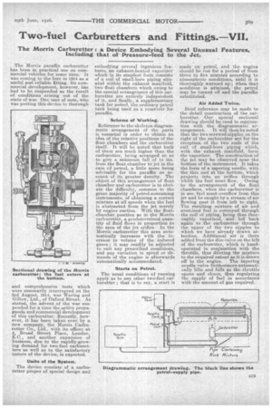
Reference to the skeleton diagrammatic arrangement of the parts is essential in order to obtain an idea of the relative positions of the float chambers and the carburetter itself. It will be noted that both of them are much higher than the carburetter, being arranged so as to give a minimum fall of 14 ins. from the float chamber to jet in the case of petrol, a little more being advisable for the paraffin on account of its greater density. The object of this arrangement of float chamber and carburetter is to obviate the difficulty, common to the great majority of petrol-consuming instruments, of obtaining a correct mixture at all speeds when the fuel is abstracted from the jet merely by engine suction. With the fioatchamber, position as in the Morris carburetter, a predetermined quantity of fluid flows in proportion to the area of the jet orifice. In the Morris carburetter this area automatically increases with the increase in volume of the induced gases; it may readily be adjusted to soft any prescribed conditions, and any variation in speed or demands of the engine is afterwards automatically accommodated.
Starts on Petrol.
The usual conditions of running apply as to any other two-fuel carburetter ; that is to say, a start is
made on petrol, and the engine should be rim for a period of from three to five minutes accordin to atmospheric conditions, until it is thoroughly warmed up ; when that condition is attained, the petrol may be turned off and the paraffin substituted.
Air Added Twice.
Brief reference may be made to the detail construction of the carburetter. Our special sectional drawing should be read in conjunction with the diagrammatic arrangement. It will then be noted that the two screwed nipples on the right of the carburetter are for the reception of the two ends of the coil of small-bore piping which, with the exhaust manifold, form the vaporizer. The construction of the jet may be 'observed near the bottom of the instrument. It takes the form of a tapering needle, with the thin end at the bottom, which projects into an orifice through which the fuel must flow. Owing to the arrangement of the float; chambers, when the c.arburetter is in use, fuel must, overflow from this jet and be caught by a stream of air flowing past it from left to right. The resulting mixture of air and atomized fuel is conveyed through the coil of piping, being thus thoroughly vaporized, and led back again to the carburetter through. the upper of the two nipples to which we have already drawn attention. Additional air is there added from the disc valve on the left of the carburetter, which is handoperated in conjunction with the throttle, thus diluting the mixture to the required extent as it is drawn off to the engine. The tapering needle valve fiirthermore automatically lifts and falls as the throttle opens and closes, thus regulating the supply of fuel in accordance with the amount of gas required.