


Patents Completed.
Page 38
If you've noticed an error in this article please click here to report it so we can fix it.
Complete specifications of the following patents will be sent to any address in the United Kingdom upon receipt of eightpence per copy at the Sale Branch, Patent Office, Holborn, W.C.
GREASE CUPS. —Showell. — N o. 27,326, dated 24th November, 1910.—In this specification there is described a grease cup as applied to the shackle pin by which the spring of a motorcar is supported in position. The feature of the invention lies in the provision upon the exterior of the cup of a spring claw or scraper whose free end extends beyond the cup and is formed to engage a screw thread, so that the latter is scraped and cleaned, allowing the cup to be screwed on easily. This spring scraper may also be utilized as a snap check to the feed by the formation of suitable grooves to engage it.
MOTOR LORRY. —Harris. — Nu. 13,496, dated 5th August, 1910.—This invention relates to motor lorries and is particularly applicable for contractors' work in removing material. The top of the frame of the lorry is sloped backwards towards the rear, and the body is fitted thereon with correspondingly flanged ridges, the arrangement being such that the body can slide backwards easily. A suitable catch is provided at the forward end, and this is controlled by a handle easily accessible to the driver. When it is desired to tip the car, the lorry is brought into position, the catch is released and the car started forward with a jerk ; this, it is stated, gives the body of the lorry an impetus, and it travels down the incline, tipping when it reaches the end ; when the load has been removed the body can easily be replaced by one man.
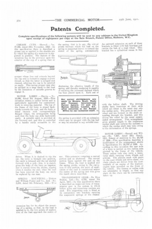
SPRING MOUNTING. —Tritton and William Foster and Co., Ltd.—No. 3,010, dated 6th February, 1911.—Ths the spring, that is to say, the virt.ial points between which the load on the spring is supported travel in toward the centre of the spring, automatically
shortening the effective length of the spring, and thereby rendering it capable of resisting the increased demand which has been placed upon it. Each end of
the spring is provided with an extension which may be integral with the top leaf or may be attached in any suitable man ner. This extension comprises a curved portion and an abutment. The curved portion bears against the pad on the frame. When the load is applied and the spring yields, owing to the curvature of this portion, the point of application of the load is transferred nearer the centre of the spring and this gives the result above described.
TRANSMISSION GEAR.—De Dion Benton, Ltd.—No. 8,722, dated 7t April, 1911.—in this specification there is described an improved form of transmission gear in the system in which hollow axles and transverse cardans are used. The supporting axle is fitted at its extremities into brackets carrying the suspension springs of the chassis An outward extension on each of these brackets is fitted with ball bearings awd carries the hub of a road wheel. This bracket has a cylindrical recess in line with the hollow shaft. The driving shafts have trunnions at their enAs which are fitted in the usual way into the cardan jaws. The jaws on the roadwheel end are formed on the shaft ex tending through the bracket, and this drives the wheel by the usual squareended arrangement. This arrangement gives greater length to the transverse cardan shaft and reduces the inclination which the cardan shaft may take owing to the deformation of the springs.
MOTOR LORRY.—Burrell and Wilson.—No. 7,867, dated 29th March, 1911, Patent of Addition to No. 20,738 of 1909.—This specification describes a modification of the arrangement shown in Specification No. 20,738 of 1909. According to this invention the rear axle of a lorry is carried on two radius rods pivoted to the frame of the vehicle. These radius rods also carry a transverse shaft carrying chain wheels and pinions. The pinions mesh with gears on the road wheels and drive them; the chain wheels are driven from the caurttershaft of an engine of the tractionengine type mounted on the front of the vehicle. The frames or radius rods are adjustable in length, so that any slack on the chain can be conveniently taken up.