


A Pneumatically Operated Clutch
Page 64
If you've noticed an error in this article please click here to report it so we can fix it.
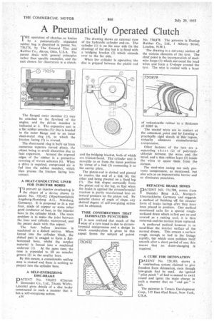
THE operation of clutches or brakes by a pneumatically *expanded rubber bag is described in patent No. 730,576, by The General Tire and Rubber Co., Akron, Ohio, U.S.A. The patent deals with general principles rather than specific examples, and the unit chosen for illustration 'is a clutch.
The flanged outer member (1) may be attached to the flywheel of the engine, arid the driven member is indicated at 2. The expansive unit is a flat rubber annulus (3); this is bonded to the outer flange and to an inner sheet-metal ring (4), to which the friction facing (5) is riveted.
The sheet-metal ring is built up from numerous separate curved plates, the object being to avoid distortion due to heat expansion. Around the exposed edges of the rubber is a protective covering of woven asbestos (6). When a drive is required, compressed air is fed into the rubber member, which then presses the friction lacing into contact.
A HEAT-CONDUCTING LINER FOR INJECTOR BORES
TO
prevent ap injector overheating is object of a device shown in patent No. 730,432 (Maschinenfabrik Augsburg-Nurnberg A.G., Ntirnberg, Germany). It is proposed to fit a wet liner, made of copper or some other good conductor of heat, in the injector bore in the cylinder block. The main problem is to make the joint between the liner and cylinder waterproof, and the patent deals with this aspect.
The liner before insertion is machined to a dished section. When forced into the cylinder block, the dished part is swaged to form a fiatbottomed bore, whilst the surplus material is forced into a machined undercut (1). At the same time, the nose is expanded to fill an annular groove (2) in the smaller bore.
By this means, a considerable sealing area is created and there is nothing to project into the cylinder bore.
A SELF-ENERGIZING DISC-BRAKE
121 A T EN T No. 730,053 (Clayton
Dewandre Co., Ltd., Titanic Works, Lincoln) gives details of a disc brake constructed in such a manner that it has a self-energizing action. The drawing shows an external view of the hydraulic cylinder end-on. The cylinder (1) is on the near side (in the drawing) of the disc but it is fitted with a bridging bracket (2) which extends over to the far side.
When the cylinder is operative, the disc is gripped between the piston rod and the bridging bracket, both of which are friction-faced. The cylinder unit is movable to or froth. the mean position by virtue of a link (3) connecting it to the carrier plate.
The piston-rod is slotted and pinned to receive the end of a link (4), the other end being pivoted on a fixed lug (5). The link slopes outwardly from the piston rod to the lug, so that when the brake is applied the circumferential reaction is partly transformed into an inward pressure on the piston rod. By suitable choice of angle of slope, any desired degree of self-energizing action can be obtained.
TYRE CONSTRUCIION THAT ELIMINATES PUNCTURES I T is now realized that much of the wear of a tyre tread is due to circumferential compression and a design in which consideration is given to this aspect forms the subject of patent No. 730,878. The patentee is Dunlop Rubber Co., Ltd., 1 Albany Street, London, N.W.1.
The drawing is a cut-away section of the various elements of the tyre. The chief point is the incorporation of steelwire loops (1) which surround the bead wires and form a U-shape around the tyre. The wire is coated with a layer of vulcanizable rubber to a thickness of 0.005 in.
The coated wires are in contact at the outermost point and by forming a practically rigid sheath at this region, virtually eliminate circumferential compression.
Other features of the tyre are a separating sh ee t (2) of polyvinylchloride between the wires and the tread, and a thin rubber layer (3) inside the wires to space them from the Carcass.
The steel-wire casing not only prevents compression, as mentioned, but also acts as an impenetrable barrier and so eliminates punctures.
REFACING BRAKE SHOES
PATENT NO. 731,788, comes from Daimler Benz A.G., St ut tga rtUnterturkheim, Germany and suggests a method of finishing off the circular form of brake facings after they have been placed in position. One method mentioned calls for a special roughsurfaced drum which is first put on and rotated as a cutting tool; it is then removed and the normal drum replaced
A preferred method however is to sand-blast the interior surfaceof the normal drums. This creates a surface rough enough to bed in the linings rapidly, but which soon polishes itself smooth after a short period of use; this means that no drum-changing is required.
A CURE FOR DETONATION
PATENT No. 729,383, shows a combustion system claimed to give freedom from detonation, even though low-grade fuel be used. An ignited "pilot patch" of fuel is caused to swirl round and ignite the main charge in such a manner that no "end gas" is left.
The patentee is Texaco Development Corp., 135 East 42nd Street, New York, U.S.A.