


Patents Completed.
Page 22
If you've noticed an error in this article please click here to report it so we can fix it.
Harrier Wheel Mounting. Shock-absorbing Hub Devices. Multiple Strand Roller Chains. Ball Bearing Improvements.
Copies of complete specifications of the patents published on this page can be obtained from the Sales Branch, Patent Office, Holborn, W.C., at the cost of sixpence for each specification.
A. E. CARTER, C. G. EDEN and HANS RENOLD LTD., No. 24,435, dated 21st December, 1914, patent of addition to No. 6786, 1914.—The accompanying drawings show two constructions of multiple strand roller chain. Alternate pitches or links are made up entirely of inner combinations, whilst the
intermediate pitches comprise an inner combination at the centre and reinforcing link plates at the outside. Each inner combination consists of a pair of 1Mk plates which are held together at each end by bushes forced into them, and the rollers surround the bushes. The reinforcing link plates on the outside are also provided with bushes, the length of these, however, being equal to the thickness of the plates only.
The chain is assembled by slippingthe inner combinations and 'outer link plates on to the studs and riveting the ends iiver On washers. This construction gives a chain with the came number of link plates in every pitch.
J. RIEEIE, No. ,19,522, dated 8th September, 1914.—In this construction, which can be applied either to a driving or nondriving wheel, the wheel-body is of the ordinary form, the spokes and rim being made of pressed steel. The hub fitting inside the wheel-body has a fixed flange on one side and a loose flange on the other, secured together by bolts in such a manner as to permit a certain amount of free dom of the two flanges relatively to one another. These flanges provide a friction-drive between the hub and the body of the wheel. The latter is supported by means of rubber blocks fitting round is hexagon portion on the hub. In the case of a driving wheel, part of the drive may be transmitted by a brake-strap tied to the rim of the wheel and acting on the brake-drum on the hub.
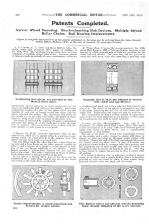
H. WADE (AKT. SVENSKA KULLAGERFABRIKEN), No. 1133, dated 23rd January, 1915,—This specification describes a ball bearing in which separate sets of balls are provided for the radial and end, thrusts. The inner ring has two grooves in which the balls move, while the outer ring is provided with
a cyfuidrical ball track and with a spherical ball track to one side of it. The centre of the sphere is arranged to one side of the plane containing the first row of balls which take the radial load, independent ball cages are used for each row. This construction permits a certain amount of axial movement of the two races relatively to one another, so that under all circumstances the shaft is easily rotatable.
CLAYTON AND CO. (HUDDERSFIELD), LTD., and V. S. EASTMENT, No. 18,955, dated Mnd August, 1914.—The object of this invention is to do away with screw-threaded parts in fixing road wheels on their shafts, and a bayonet-joint arrangement is used instead. The end of the shaft is formed with longitudinal recesses on the outside, and a collar, shaped to engage with these, is slipped on, thus providing an abutment which rotates with the shaft. • Nearer the end of the shaft circumferential grooves are formed connecting these slots. A ring of L-section has projections formed inside it to engage with these grooves, and the projections' are of such length that they fit within the longitudinal slots to enable the ring to be slid on. This ring is then turned to engage the grooves so that it cannot slide (pit endwise.
It is locked to the first ring by setscrews, 80 that it cannot rotate on the shaft, and a simple locking device is therefore provided to hold the wheel in place; a loose washer being mounted between these two rings and the wheel