


To Isolate a Seized Injection-pump Plunger
Page 36
If you've noticed an error in this article please click here to report it so we can fix it.
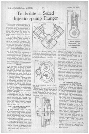
to respond to the control gear, in leave the remaining plungers free the event of seizure of one, is the object of a safety device for incorporation in multi-plunger injection pumps of appropriate type, shown in patent No. 549,209, by C.A.V., Ltd., and F. M. Evan, both of Warple Way, London, XV.3.
In the. design of pump to which the invention relates, each plunger Is rotated, for output control, by a sleeve (4) turned by a rack-bar. The new scheme specifies that the coupling between the sleeve and the plunger is not positive,. but includes a V-notched collar (1) on the plunger, which mates with a projection on a second collar (3) that is free to reciprocate but not to turn in the sleeve (4).
Normally, the rotary -adjustment is transmitted by the V-coupling, but' a seizure would disengage .it against the loading of a light spring (2).Only One projection and one notch are provided, so that if re-establishment occurs, there
can be no positional error, • ROTARY INTERNAL-COMBUSTION ENGINE
AN alternative to the reciprocating engine forms the subject of patent No. 548,827, from P. R. Boulton, Bushwood, Nightingale Lane, Chalfont St. Giles, Bucks. The engine operates by expanding its power charge in a space created between a pair of rotors of the Roots-blower type.
These are housed in a water-jacketed casing. The two rotors (2 and 4) form a substantially gas-tight joint where they make rolling contact, and on the projections (5 and 8) which slide on the casing walls. Compressed mixture is admitted by a dual rotary sleeve valve (6) to the space (7) accommodat ing the sparking plug. After firing expansion continues until an exhaint port (3) is exposed.
The engine described is a two-stage compounded unit, and port 3 leads to the inlet of the second stage. Included also in the design is a two-stage compressor for supplying the mixture. All ttese components are co-axial. The rotors have interior cooling, incoming fluid being directed to the hottest parts by pipes (1).
SINGLE-ACTING ENGINE WITH ' POWER UP-STROKE
ATWO-STROKE engine, in which combustion occurs on the underside of the piston. is the subject of patent No. 549,246, by A. Robinson, Frithsden Lodge, Berkhamsted, Herts. The design b is applicable to either sparlor compression-ignition engines.
An embodiment of the invention to V-type engine is illustrated, the crankpins being set 180 degrees apart. Each piston has two diameters—a small one (3) carrying the gudgeon-pin and functioning as a piston rod and crosshead, and a larger diameter at 6, con di-I.' --stituting the effective piston, which works in the main cylieder. Combustion occurs in the annular space (4) and it is this that gives the working stroke its outward direction. The head por tion of the cylinder is used as a chvging pump.
In action, the engine on the in-stroke draws in mixture (or air, in the case of an oil engine) via port 1. On the succeeding out-stroke, so soon as port 1 is covered, pre-compression takes place, the charge being stored in the transfer.
port (5). At the end of the out-stroke this port (5) is opened to the combustion space and the charge enters, whilst the exhaust products escape out of another port (2) on the other side of the cylinder.
Intermixture is discouraged by the obstruction created by the presence of what may be described as the piston stem (3), the charge dividing into two streams which sweep around the combustion space, evactiating the burnt gases. Claims made for this unit include simplicity, easy manufacture and repair, with special reference to cylinder repair, absence of cylinder-head gasket, of liability to piston overheating, and of need for admixture of lubricant with the fuel, and adaptability to supercharging.
LC. TURBINE WITH RECIPROCATING COMPRESSOR
SUBJECT of patent No. 548,699, from 3. H. Lincoln, 19a, Clarence Road, Derby, is an engine operating on the compression-ignitien principle, having air-compressing cylinders supplying an air charge, into which the fuel is injected, the resulting combustion gases being led to a vaned turbine wheel which forms the power member.
In the drawing the air-compression pistons (3) inspire air through ports (5) opened at b.d.c., and on the up-stroke compress it into a 'space ,(2) in which the injector is located. Ports in the side of the chambers (2) lead to •a vaned turbine wheel (7) which is driven by the exhaust products. T4 isolate space from the turbine during the suttion stroke, a timed slide-valve (1) controls the,connecting ports.
After the gases 'have passed the turbine, they are collected by the enclosing casing and finally issue from the ports (6). These may, with advantage, have a suction applied to them.
The compressor pistons, four in number,_are driven by a grooved cam (4), the connecting rods being fitted with followers.