


A Variable-compression Engine
Page 54
If you've noticed an error in this article please click here to report it so we can fix it.
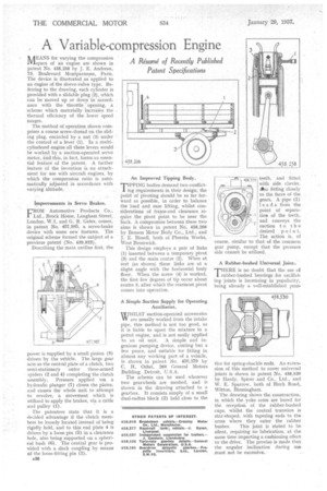
jfEANS for varying the compression alspace of an engine are shown in patent No. 458,258 by J. E. Andreau, 73, Boulevard Montparnasse, Faris. The device is illustrated as applied to an engine of -the sleeve-valve type. Referring to the drawing, each cylinder is provided with a slidable plug (2), which can be moved up or down in accordance with the throttle opening, a scheme which materially increaSes the thermal efficiency of the lower speed ranges.
The method of operation shown comprises a coarse screw-thread on the sliding plug, encircled by a nut (3) under the control of a lever (1). In a multicylindered engine all these levers would
be worked by a suction-operated servo
. , motor, 'and this, in fact, forms an essential feature of the patent. A, further feature of the invention is an attachment foruse with aircraft engines, by which the compression ratio is automatically adjusted in accordance with varYing altitude.
Improvements in Servo Brakes.
CRC)bil Automotive Products Co., Ltd., Brock House, Langlia.m Street, London, W.1, and G. R. Gates, comes, in patent No. 457,985, a servo-brake device with some new features. The original scheme formed the subject of a previous patent (No. 439,923).
Describing the main outline first, the power is supplied by a small pinion (8) driven by the vehicle. The large gear acts as the central plate of a clutch, two semi-stationary outer three-armed spiders (2 and 4) completing the clutch assembly. Pressure applied via a hydraulic plunger (7) closes the plates, and causes the whole unit to attempt to revolve, a movement which is utilized to apply the brakes, via a cable and pulley (1).
The patentees state that it is a decided advantage if the clutch members be loosely located instead of being rigidly held, and to this end plate 4 is driven by a loose pin (5) in a clearance hole, also being supported on a spherical bush (6). The central gear is provided with a slack coupling by means of the loose-fitting pin (3).
436 An Improved Tipping Body.
TIPPING bodies demand two conflicting requirements in their design; the point of pivoting should be so far forward as possible, in order to balance the load and ease lifting, whilst considerations of frame-end clearance require the pivot point to be near the back. A compromise between these two aims is shown in patent No. 458,206 by Benson Motor Body Co., -Ltd., and J. E. Bissell, both of Phcenix Works, West Bromwich.
This design employs a pair of links (1) inserted between a temporary pivot (3) and the main centre (2). When at rest (as shown) these links are at a slight angle with the horizontal body floor. When. the screw (4) is worked, the first few degrees of tip occur about centre 3, after which the rearmost pivot comes into operation.
A Simple Suction Supply for Operating
WWHILST suction-operated accessories ifif are usually worked from the intake pipe, this method is not too good, as it is liable to upset the mixture in a petrol engine, and is not easily applied to an oil unit. A simple and ingenious pumping device, costing but a few pence, and suitable for fitting in almost any working part of a vehicle. is shown in patent No. 458,379 by C. H. Oshei, 260 General Motors Building, Detroit, U.S.A.
The scheme can he used wherever two gearwheels are meshed, and is shown in the drawing attached to a gearbox. It consists simply of a small dual-radius block (2) held close to the teeth, and fitted with side cheeks, Also fitting closely to the faces of the gears. A pipe (1) leads from the point of separatiom of the teeth, and conveys the suction to the desired poin t. The action is, of course, similar to that of the common gear pump, except that the pressure side cannot be utilized.
A Rubber-bushed Universal Joint
TfIERE is no doubt that the use of rubber-bushed bearings for oscillating joints is increasing in popularity, being already a well-established prao.
tice for spring-shackle ends. An extension of this method to cover universal joints is shown in patent No. 458,530 by Hardy, Spicer and Co., Ltd., and W. E. Sparrow, both of Birch Road, Witton, Birmingham.
The. drawing shows the construction, in which the yoke arms are bored for the reception of the rubber-bushed cups, whilst the central trunnion is star-shaped, with tapering ends to the arms where they enter the rubber bushes. This joint is stated to be silent, requiring no lubrication, at the same time imparting a cushioning effect to the drive. The proviso is made that the angular inclination during use must not be excessive.