A New Atkinson Six-wheeler Announced
Page 34

Page 35

If you've noticed an error in this article please click here to report it so we can fix it.
A Gardner-engined 10 tonner Weighing Under 5 Tons, Unladen, and Affording a Body Space 21 ft. Long. Shorterwheelbase Model Also Available
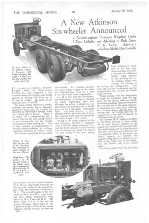
TN response to a demand. Atkinson 1 Lorries (1933), Ltd., Marsh Lane, Preston, has just completed a sixwheeled chassis of straightforward design capable of dealing with loads up to 10 tons in weight. Its price, in the standard form, is £1,365.
The frame of this vehicle is a sturdy, although not unduly heavy, structure carried by three axles, all of which are mounted on semi-elliptic springs. Only the central axle is driven. There is no bogie, but a compensating bar is placed between the rear spring shackle of the driving axle and the forward spring shackle of the trailing axle. Thus a large measure of compensation is afforded—quite sufficient for ordinary conditions of service on " made roads.
The chassis is produced in two wheel.
base lengths : the short model measures 11 ft. 11 ins., between the front and the driving axles, whilst, in the long-wheelbase form, the equivalent• dimension is 13 ft. The overall lengths of the two types are 24 ft. and 26 ft. respectively, and they afford, respectively, body spaces of 17 ft. 6 ins. and 21 ft. The frame width is 3 ft. 2 ins, and the ground clearance when laden 11 ins. A platform height of 3 ft. 9 ins, can be obtained without cutting the floor fOr
A32 wheel-arches. For taxation purposes the exact chassis weight of the short and long-wheelbase types are 4 tons 2 cwt. and 4 tons 3 cwt. respectively.
ks will be seen from the accompanying illustrations, the design is planned on sound engineering lines and, although the vehicle is clearly not intended for cross-country work, it should prove to be a thoroughly roadworthy type. The main channels are quite straight, both in plan view and in elevation, and are 8 ins, deep for practically the whole length of the vehicle,
Owing to the design adopted for the rear springing, the load is supported over a distance of approximately 8 fr., and the front spring eye of the driving axle is situated only about 8 ft. behind the rear fixing. of the front spring.
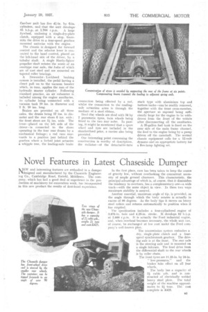
Cross bracing is taken care of by four deep channel-section members, a measure of additional rigidity being afforded by the pivoting bar for the balance beams connecting the springs of
the driving and trailing axles. This cross bar is 21 ins, in diameter and the compensating bars operate on needleroller bearings.
Whilst dealing with the suspension, it might be mentioned that the sup-, ports for the spring bolts are deeply ribbed steel castings which envelop both the web and face of the main channels. It should here be added that, although the standard design calls for only one driving axle, the trailing axle can be replaced by a live axle if desired—at additional cost, of course.
The Gardner 5L.W. engine is mounted in the frame virtually at three points. At the rear, bearers, attached to the engine body immediately forward of the flywheel housing, rest on frame brackets with fibre pads interposed between the two elements, whilst, at the front, two similar supports are provided, the brackets being placed as closely as possible to the centre line of the engine ; they arc, indeed, only a few inches apart. , It will be recalled that this particular
Gardner unit has five 41-in. by 6-in. cylinders, and .that the unit develops
S5 at 1,700 r.p.m. A large flywheel, enclosing a single-dry-plate clutch, equipped with a stop, transmits the drive to a four-speed gearbox mounted unitwise with the engine.
The chassis is_ designed for forward control and the selector lever is connected to the hand control, placed on the left-hand side of the driver, by a tubular shaft. A single Hardy-Spicer propeller shaft rotates the worm of an overtype rear axle, the hubs. of which are of cast steel and are mounted on tapered roller bearings.
A Dexvandre Lockheed braking system is installed, the ,pedal having a direct pull on to the vacuum booster which, in turn, Applies the ram of the hydraulic master cylinder. Following standard .practice, an air exhauster is included among the engine auxiliaries, its cylinder being• connected with a vacuum tank 10 ins, in diameter and 2 ft: 10 ins. long.
Brakes are provided on all three axles, the drums being 17 ins, in diameter and the rear shoes 6 ins. wide : the front shoes are 31ins, wide. The lever—placed on the left side of the driver—is connected to the shoes operating in the four rear drums by a mechanical linkage ; a rod runs rearwards to a position just behind the gearbox where a forked joint actuates a whipple tree, the leading-axle brake connection being effected by a rod, whilst the connection to the 'trailingaxle actuation arms is through the medium of a steel ribbon.
Steel disc wheels are shod with 34 by 7 pneumatic tyres, twin wheels being fitted to the two rear axles. In passing, it might be mentioned that a spare wheel and tyre are included in the standardized price, a carrier also being provided.
One interesting point concerning, the construction is worthy of description, the radiator—of the detachable-tube stack type with aluminimn top and bottom tanks—can be readily removed, together with the front cross-member, the aperture so exposed being sufficiently large for the engine to be withdrawn from the front of the vehicle after disconnecting all the auxiliaries.
A 35-gallon fuel tank is fixed on the near side of the main frame channel, the feed to the engine being by a pump driven off the camshaft. The normal chassis equipment calls for a 12-volt dynamo and an appropriate battery for a five-lamp lighting set.


