


Patents Completed.
Page 22
If you've noticed an error in this article please click here to report it so we can fix it.
Complete specifications of the following patents will be sent to any address in the United Kingdom upon receipt of eightpence per copy at the Sale Branch, Patent Office, Holborn, W.C.
An Adjustable Mudguard.
Percy Stock.—No. 17,764, dated 4th August, 1911,—This specification describes a mudguard to prevent side splashing of mud from motor-vehicle wheels. The guard consists of a rubber flap suspended from a light iron frame which is hung from a nose-piece or nut projecting from the axle-cap of the wheel. The flap is made adjustable in height by means of a telescopic joint by which the lower part of the frame is secured to the upper part.
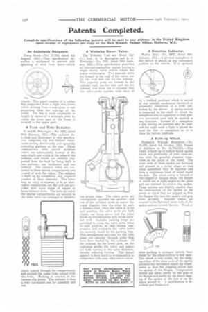
A Tank and Tube Radiator.
E. and II. Behringer.—No. 1803, dated 24th January, 1911.—The radiator described and illustrated in this specification comprises top and bottom watertanks having downwardly and upwardly extending portions at the rear. These communicate with special members which are substantially formed of the same depth and width as the tubes of the radiator and which are suitably supported from the tank by being built in two portions, one horizontal and one vertical. The radiator tubes are connected to these special compartments and consist of wide flat tubes. The radiator is built up by assembling any required [Lumber of these elements. The tubes may be wavy or sinuous, or in an alternative construction are flat and are provided with wavy strips of copper or brass between them. The bolts by which the special compartments are secured to the water tanks are arranged in thimbles
which extend through the compartments and exclude the water from contact with the bolts. Packing is inserted at the various slip joints. The radiator is thus a very convenient one for assembly and use.
A Wolseley Sleevl Valve.
The Wolseley Tool and Motor Car Co., Ltd., A. A. Renington and A. J. Rowledge.—No. 1421, dated 19th January, 1911.—This specification describes an internal-combustion engine having a single sleeve valve within which the piston reciprocates. Two separate ports are formed in the wall of the valve, one for the inlet and one for the exhaust. Two separate ports are formed in the cylinder wall, one for inlet and one for exhaust, and these are so situated that the valve ports register with them at the proper time. The valve ports are conveniently opposite one another, and one of the cylinder ports is nearer the crank chamber than the other by such a distance that, when the valve is in its mid position, the valve ports are both closed, one being above and the other below its corresponding port in the cylinder wall. Suitable packing rings are provided to cover the valve ports when in mid position, so that during compression and explosion the valve ports are securely closed by the packing ring. This arrangement provides for the inlet gases not entering through ports that have been heated by the exhaust. if the exhaust be the lower port, on the explosion stroke the valve and piston are both moving in the same direction, thereby reducing friction. This design appears to have much to recommend it in comparison with seine other sleeve valves.
A Direction Indicator.
Walter Kerr.—Uo. 2507, dated 30th January, 1911.—A pivoted semaphore or disc device is placed at any convenient position on the vehicle. It is operated
by a toothed quadrant which is moved by any suitable mechanical electrical or pneumatic connection to a lever controlled by the driver. A spring-control is connected to the shaft on which the semaphore arm is supported so that positive movement need only be applied in one direction. Instead of a semaphore a disc having an aperture may be used, and for night work a light is placed behind the disc or semaphore so as to show its various positions.
A Built-up Wheel.
Frederick William Brampton.—No. 21,878, dated 4th October, 1911, Patent of Addition to No. 16,795/1911.—This wheel is built up of hollow metal spokes which are preferably of oval cross-section with the greatest diameter transverse to the plane of the wheel. The inner ends of these spokes are flattened and pressed to a sector shape so that when assembled they fit together and form a continuous band of metal round the hub. The wheel-centre is formed of two cupped or flanged shells, the flanges of which are at right angles to the plate and are notched to receive the spokes. These notches are slightly smaller than the cross-section of the spokes at the points at which they are gripped so that the flanges bite into the spokes and grip them securely. Annular plates are secured to the flattened inner ends of the spokes and are riveted thereto. Wood or other packing is arranged outside these plates for the wheel-centres to bed upon. This wheel is very stable, for the wedging action of the inner ends of the spokes prevents any movement round the wheelcentre as does the gripping action into the spokes of the flanges. Compression strains are taken partly by the grip of the flanges and partly by the direct bearing of the spokes on the hub or on the sleeve around it. A modification is described and illustrated.