


Hydraulic-transmission Inventions
Page 62
If you've noticed an error in this article please click here to report it so we can fix it.
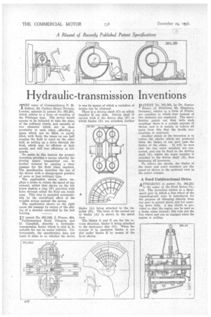
MHE name of Commandatore P. if.
Salerni, 23, Canton House Terrace, London, appears in patent No. 361,281, which relates to a form of coupling of the Fiittinger type. The device would appear to be intended to take the place of the ordinary clutch, and consists of two elements which are in close proximity to each other, affording a space which can be filled, or partly filled, with fluid, the vanes on one half causing the fluid to react on the other half, so setting up a drive through the fluid, which may be efficient at high speeds, and will lose efficiency at low speeds.
To assist in this feature the present invention provides a means whereby the driving power transmitted can be further reduced by opening a clear passage for the fluid when required. The specification describes the use of the device with a change-speed gearbox of more or less ordinary type.
The application shown above employs a brake to reduce the speed of one element, whilst that shown on the left below depicts a ring (F) provided with holes through which the fluid can freely pass. This ring is operated automatically by the centrifugal effort of the weights acting against the spring.
The application shown on the right opens the passage by means of the sliding of a member controlled by the ball bearing.
IN patent No. 361,342, S. Fraser, 424, Parliamentary Road, Glasgow, and D. Campbell, describe a hydraulictransmission device which is said to be suitable for use on motor vehicles. Unfortunately, the specification does not make it plain to us whether the device is one by means of which a variation of torque can be obtained.
There is a driving shaft (C) on which impeller B can slide. Driven shaft N carries with it the driven disc (F) to which blades (E) are attached, further
blades (A) being attached to the impellor (B). The form of the second set of blades (A) is shown in the small view.
The blades G and E are for the reverse direction, bladesG being attached to the stationary disc (0). When the reverse is in operation blades A are slid under blades E by means of the lever shown. PATENT No. 361,i$61, by Dr. Gustav
Bauer, of Mittleweg 82, Hamburg,, Germany, relates to a form of Fottinger coupling in which four instead of two elements are employed. The specification points out that, with such couplings there is a certain amount of thrust, and it is mainlyto relieve. all parts from this that the double con
_ struction is employed. • Another object of the invention is to reduce the shocks which are produced when the blades of One part pass the blades of the other. It will be seen. that the two outer members are connected, and can be fixed to the driving shaft (7), whilst the inner member is attached to the driven shaft (8), thus balancing all pressures. • To relieve the shocks, the blades of the inner and outer members are disposed as shown in the sectional view in the centre column.
A Ford Unidirectional Drive.
APPEARING in patent No. 361,211 is the name of the Ford Motor Co., Ltd. The invention relates to a threespeed gear in which a free wheel of the expanding-coil type is introduced for the purpose of changing silently from top gear to second seed, and for coasting down hills. A (.14)g clutch is provided so that the engine can be used as a brake when desired ; this cuts out the free wheel and can be engaged when the engine is pulling.