


Superheater for Wet-blast Gas Producer
Page 26
If you've noticed an error in this article please click here to report it so we can fix it.
A Resurhi of Patent Specifications That Have Recently Been Published. Copies may be Obtained from the Patent Office. Price I!each.
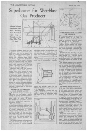
--ro convert the water supply to a gas1 producer into superheated steam before entry into the fire zone is the object of .a steam generator shown in patent No. 537,904 by Vauxhall Motors, Ltd., Kimpton Road, Luton, and others, Ineoperation, the heat for the formation of the steam is obtained from the outgoing gases by passing them through a heat-exchanging device which also functions as a cyclone cleaner. The steam is said to leave this device at about 200 degrees C.
Outgoing gases from the producer enter pipe 5 and divide into two streams which travel around the inner chambers (3) and finally make an exit from the central tubes (2) which lead to the engine intake. Meanwhile, air enters via a venturi (1) and is charged with water from a jet in the throat, which is fed in turn irate a float chamber. The water-laden air circulates around the exterior of the gas-chambers (3), and is converted into superheated steam in the process. The steam leaves via pipe 4, which leads to the intake of the producer.
HYDRAULIC-TRANSMISSION • REAR-ENGINE LAYOUT
AN hydraulic torque-converter, intended for :year-engined vehicles having the engine mounted crosswise, and &lying the axle via an angular propeller, shaft, is shown in patent No. 537,811 by a specialist in the matters, A.P. Ljungstronis Angtnrbin, of Stockholm, Sweden.
The-system employs a torque-converter operating on known principles, the patent being cpncerned with the coupling arrangements in the transmission. A normal plate-clutch is located between engine and converter; and is used for starting. It does not, however, have to slip with any appreciable load, as the hydraulic gear takes little power to set it in motion, and the friction plates should therefore last indefinitely.
The torque-converter performs all the low and medium-gear work, but top speea is obtained 'by a direct Coupling
dog-clutch between the engine and the output bevels, the hydraulic gear being then out of action. The dog-clutch is fitted with synchronizing mechanism which prevents engagement at differing speeds. '
A mechanical reverse gear of the cpicyclic type is incorporated. Another
patent, No. 537,840, deals with the details of the synchronizing mechanism of the clog-clutch.
Chief advantagefor the design is that it as. a low., overall length, a feature of importance when the engine is slung crosswise in the frame.
A CARBURETTER FOR PARAFFIN OR CREOSOTE
TO enable an engine to be run on the heavier types of oil such as paraffin or creosote is the object ofa design of carburetter shown in pateet No. 537,779 by G. Mangoletsi, 4, King's Road, Ashton-on-Mersey, Cheshire. In this system, the normal throttle controls only -the air supply, the fuel, in the form of a rich airLemulseen, being separately contrbiled and piped to points adjacent to the inlet valves.
Referring to the drawing, 6 is the induction manifold, controlled by the usteal throttle (7). The air, before reaching the throttle, must open a spring:loaded valve (10) thus creating a variable degree of suction in tile
space (9). .
The exhaust matifold (4) is provided with a closed chamber (5) for the perpose of heating the fuel-air emulsion. The latter is formed in an oil-supplied carburetter (8) of which the tapered jet-needle is coupled to the accelerator via lever 1. Rich mixture passes up pipe 2. through the heater chamber and via pipes 3 and 12 into proxiinity with the inlet valves.
For starting, petrol is used, a normal type of cerbutetter (11) being additionally fitted. This is arranged to be put into operation by a special control, being also coupled to the lever (I) so that idling is always performed on petrol.
CYLINDER-HEAD DEVICE TO GIVE 100 PER CENT. SCAVENGE THE usual four-stroke engine has
only about five-sixths of its cylinder 'volume evacuated during the exhaust stroke, the compression space accounting for the remainder: A scheme to enable ,a complete scavenge to be achieved is shown in patent No. 537,821 by J. and 0. Middleton, Onslow House, Meg-ham Down, Hailsham, Sussex.
In this scheme, the piston is arranged to approach the cylinder head with the minimum practicable clearance, the compression space being formed by a separate small cylinder attached to the head. The drawing shows such a cylinder placed at right angles to the main cylinder.
Inside this small cylinder is a speingloaded piston which is forced outwards during the compression and power strokes, thus creating a compression space. When the pressure fails at the end of the exhaust stroke howeVer, the spring moves the. piston, and thus expels the last traces of the exhaust gas.