


Leading Maker Designs Integral Bus Frame
Page 17
If you've noticed an error in this article please click here to report it so we can fix it.
Unit-construction Body and Chassis, in Which Tubular Members and Metal Sections Serve Important Functions, Designed by the Leyland Concern
STAGNATION of thought in the field of design does not appear to be a consequence of the abnormal conditions of the present. Descriptions of many new ideas from numerous manufacturers have been published in this paper recently, and now comes from Leyland Motors, Ltd., Ham Works, Kingston-on-Thames, a scheme for the construction of a chassis frame for passenger vehicles, notably trolleybuses, which constitutes an outstanding• departure from current practice.
• Virtually, the chassis frame and the body frame in this design are integral, although, in considering. the structure, it may be desirable to refer to certain members as essentially chassis parts or bogy parts. For example, the main longitudinals and cross-members come under the first heading,_ whilst the body pillars, although attached by rivets and contributing to the strength of the chassis, are classed, as their name implies, as units of bodywork.
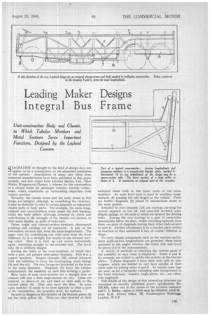
Tubes, angleand channel-section members, sheet-metal pressings and castings are all employed. A pair of the first-named, on each side, form the main longitudinals. The upper tube (4) (considering one side) runs from the front bulkhead (1) in a straight line nearly to the forward driving wheel. Here it is bent up and curves horizontally again, remaining straight to the extreme rear. The lower tube (6) is similarly shaped.
Joining the tubes at the cross-members, of which they form a part, are pressed sheet-metal brackets. Part 9 is a typical specimen. Shaped channels (12) extend forwards from the bulkhead to carry the front-spring, front fixings (8) and the cab. The rear 5xings are bracketed to the front of the main structure. Diagonals (7) brace the tubular longitudinals, the assembly on each side forming a girder.
Main units of each cross-member are a straight tube or channel (10) and a bent angle-section tie (11). These are strutted, as shown at 14, and fixed at their ends to the bracket plates (9). They also carry the floor, In some cases member 11 needs to be bent upwards to clear a part of the transmission, the propeller shaft, for instance.
Secured to flanges on the outsides of the bracket plates (9) are the body pillars (2). These are also strutted at their extended lower ends to the lower units of the crossmembers. At waist level each is fixed to auxiliary longitudinals (5) running the full length of the vehicle. There are further diagonals (3) joined to intermediate struts of the main girders.
Attached to rear channels (13) are castings carrying the central supports of the offand near-side inverted semielliptic springs, to the ends of which are secured the driving &xles. Joining the two castings is a pair of cross-tubes immediately below the floor, whilst extending upwards from them are pairs of diagonals having their other ends secured to tube 6. Further attachment is to a bracket plate similar in function to that numbered 9 but, of course, different in shape.
To carry chassis components such as the traction motor, short angle-section longitudinals are provided, these being mounted in the angles between the struts (14) and lower tie pieces (11) of the cross-members.
A variety of methods of attaching the various parts of the assembly to each other is employed. Tubes 4 and 6, for example, are welded to saddle-like sockets on the bracket plates. Tubular diagonals 7 have their ends split to take tongues, which are welded in and have saddles at their other ends for joining tubes 4 and 6. In certain cases lugs are used, as for a forwardly extending tube incorporated in the front structure. Gussets, angle-pieces, etc., are otherwise employed.
Full details of the design of this interesting structure are contained in recently published patent specification No. 537,955, taken out in the names of the Leyland company and C. C. Bailey, copies of which may be obtained, price Is., from H.M. Patent Office, 25, Southampton Buildings, London, W.C.2.