


A Vehicle-borne Loading Ramp
Page 64
If you've noticed an error in this article please click here to report it so we can fix it.
DATENT No. 723,723, comes from
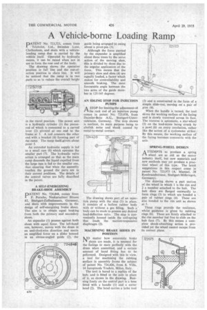
Telehoist, Ltd., Swindon Lane, Cheltenham, and deals with a vehicleloading ramp that is carried by the vehicle itself. Operated by hydraulic means, it can be raised when not in use to form the rear end of the body.
The drawing shows the operative position in full line and the out-ofaction position in chain line. It will be noticed that the ramp is in two parts so as to reduce the overall height in the travel position. The power unit 's a hydraulic cylinder (I) the pistonrod of which is connected to a curved lever (2) pivoted at one end to the frame at 3. A rod connects the other end with a bracket (4) forming part of the ramp. The ramp itselfepivots about point 5.
An extended hydraulic supply is led to a small ram (6) which operates the smaller part (7). The hydraulic valve action is arranged so that as the main ramp descends the liquid expelled from the large ram is fed to the smaller one, thus ensuring that when the assembly touches the ground the parts are in their correct positions. The details of the control valves are fully described in the patent.
A SELF-ENERGIZING BRAKE-SHOE ASSEMBLY
PATENT No. 724,848, comes from F. Porsche, Neckarsulmer Strasse 85, Stuttgart-Zuffenhausen, Germany, and deals with improvements in the design of self-energizing brake shoes. The aim is to obtain equal braking from both the primary and secondary shoes.
An expander (1) presses against both shoes with equal force. The left-hand one, however, moves with the drum in an anti-clockwise direction and exerts an amplified force on a slider housed in an obtuse-angled guide (2), the guide being arranged to swing about a pivot-pin (3).
Although the force exerted by the expander is amplified about three times by the servo action of the moving shoe, this is divided by three due to the angular application of the force. This means that the primary shoe and shoe (4) are equally loaded, a factor which makes for controllability and smooth braking. The most favourable angle between the two arms of the guide member is 125-145 degrees.
AN IDLING STOP FOR INJECTION PUMPS
ASTOP for limiting the adjustment of the rack rod of an injection pump comes in patent No. 725,078, from Daimler-Benz A.G., Stuttgart-Unterttirkheim, Germany. The stop shown is resilient, its main purpose being to abolish noise and shock caused by metal-to-metal contact.
The drawing shows part of an injection pump with the stop (I) in place. It consists of a hollow rubber body with or without a gas filling. Such a ' body can be made to possess any desired load-deflection ratio. The stop is conveniently housed inside the coil-spring that loads the suction-responsive diaphragm (2).
MACHINING BRAKE SHOES IN POSITION
NO matter how accurately brake shoes are made, it is unusual for the facings to mate perfectly with the drum when assembled, and a certain amount of hand fitting has to be pefornned. Designed with this in view, a tool for machining the rubbing surface in assembly forms the subject of patent No. 724,426, from S. Villa, 14 Jacopinoda Tradate, Milan, Italy.
The tool is bored to a replica of the hub, and is fitted to the axle in place of it, as shown in the drawing. Running freely on the central part is a boss fitted with a handle (I) and a cutter head (2). The head carries a lathe tool (3) and is constructed in the form of a simple slide-rest, moving on a pair of pins (4).
When the handle is turned, the tool skims the working surface of the facing and is slowly traversed across its face. The traverse is automatic, a star-wheel (5) on the lead-screw being struck by a pawl (6) on every revolution, rather like the action of a cyclometer striker. By this means, the working surface of the facing becomes concentric with the axle.
SPRING-WHEEL DESIGN
ATTEMPTS to produce a spring wheel are as old as the motor industry itself, but new materials and new methods may yet produce a practical wheel of this type.. The latest suggestions in this respect come in patent No. 723,975 (A. Mantzel, 28 Renabrandtstrasse, Stuttgart-Mohringen, Germany).
The drawing shows a part section of the wheel in which 1 is the rim and 2 a member attached to the hub. The hub discs are flanged 'outwardly to form rings (3) to which are bonded a pair of rubber rings (4). These are also bonded to the rim unit as shown at 5.
These rings provide the resilience, whilst guidance is given by rubbing rings (6). These are firmly attached to the rim member but free to slide on the hub face (7). By this means a complete shock-absorbing action is provided yet the wheel cannot escape from its correct plane.