


TIPS ON SPRINGS, AXLES AND FRAMES.
Page 29
If you've noticed an error in this article please click here to report it so we can fix it.
Useful Hints from Our Driver and Mechanic Readers.
AN interesting point is brought out in a Jotter from "0.8.," of Sheffield. He drives, he tells us, a vehicle which is used as a motor coach in summer. and as a 4-ton lorry in the winter. Apparently it is sprung—as regards the front axle, at least, as a motor coach—and trouble has, in consequence, developed during the winter, the front springs having more than once given way under the stress of conveying four tons of dead weight.
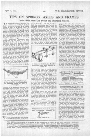
This unfortunate occurrence happened—for the last time, it is now heped—near the end of the winter of 1922-1923, both front springs breaking and being replaced by new ones, which, in _view of the fact that the spring months were close at hand, were again ordered to be of dimensions suitable for motor coach purposes. When the beginning of the winter just past arrived and the time for reconversion for loadcarrying purposes fell due, " C.S." took matters into his own hands, being determined not to have any more spring breakages, and at the same time deciding not to buy spare springs. He took a couple of leaves from the broken springs and cut them down to the size and shape indicated on the accompanying sketch, in which the pieces of spring are seen to be somewhat less than half the length of the complete spring. These were arranged on the top of the springs proper, and secured, as to their inner ends, under the existing spring clips, and as to their outer extremities by clips of special design, made from flat bar steel, and secured by transverse belts beneath the spring. The winter is now past, so far as the calendar is concerned, and the lorry is about to be reconverted once mere. No trouble has been experienced with the springs, and the extra pieces are to be put away, ready for use again when the motor coaching season again ends. Incidentally, "C8." remarks that a couple of half leaves with the necessary clips are useful spares, and may come in very handy in case of any actual spring breakage. We award the prize of 15s. to the writer of this letter.
THE most vulnerable part of a chassis, if we except the radiator, is the front end of the frame. " W.S.S.," of Mansfield, has apparently had several unfortunate experiences, which have resulted in buckled dumb-irons, and the methods which he has used to straighten them will undoubtedly be of u.se to many other readers of this page.
The principal item of his equipment is a section of steel rail, 6 ft. in length. This is bent near one end, as shown in the sketch, and is fitted with an eyebolt, the hole in which is the same as that in the front spring, so that it can accommodate the shackle pin. Substantial clips, of 2-in. by -a-m. plate, and I-in, bolts serve to secure the rail to
the top of the frame in such a position that, with the shackle pin through the eyes in dumb-iron and eye-bolt, the latter will pass through the hole in the rail and receive a nut as shown, The bent portion of the frame must now be heated. This may be done 'by means of a powerful blow-lamp, or by a field forge fire. If the forge happens to be inconveniehtly high, then brick up to the frame, enclosing the bent part, and direct the flame from the forge on to it by means of 1-in. or 11-in. gas or steam-piping. As the frame reaches the desired tempera,ture, screw up the nut of the eye-bolt and gradually take out the bend.
The slight cracks or flaw at the point marked "A" in the sketch will _still be a weak part, and the frame must be stiffened there by a strengthening plate of thickness, bolted along the side of the frame-member.
WE have reason for complaint against " A.G. r." of London. He sends us two very clear drawings, which have obviously taken some time and trouble to prepare,but not a line of explanation. We understand his drawings well enough, and, accordingly, have set ourselves the task of supplying the missing information. " A.G.P.'s" suggestions, although good in themselves, are not, likely to prove very acceptable to many readers, as they involve considerable expenditure in the provision of apparatus to meet, a special contingency, for the risk of breakage of an axle sleeve is, in these days, comparatively remote. Of the two sketches, that marked " A" shows the procedure to be adopted in case of a breakage of an axle which will allow of a bolt being passed through the differential from end to end of the
axle. In such circumstances a short piece of tubing would replace the piece of broken sleeve, and it would be held in place, as shown, by a keg bolt, so that the lorry could then be conveniently towed home, without recourse teflifting tackle and special trollies.
Sketch " B" shows what would have to be done with an axle which would not permit of the passage of a bolt right through the centre, as shown in the other sketch. :In a case of this sort a special auxiliary sleeve would have to be made and kept in stock.This sleeve is bored right through to accept a central bolt or screw. It is then counterbored, as shown, and supplementary inner sleeves, marked A and B in the sketch, fitted. A is tapped to accommodate the end of the central screw ; B is a fit on that screw. Pegs are fitted to prevent these inner sleeves from turning. The inner screw has a. square on its outer end, is screwed at its inner end and. fitted with a collar to engage the outer face of the sleeve• B.
Two sets of hardened and pointed pins are located inside the auxiliary sleeve, as shown, in such a way that, as the central screw is tightened, these pegs ride up the tapering inner ends of the sleeves A and B, and are forced into close contact with the inner surface of the actual axle sleeve, thus holding the auxiliary sleeve in place.
A guide bush, to locate the central screw, may be found_ to be necessary, and one is actually shown in tlir. sketch.