


An Automatic Hydraulic Transmission A TRANSMISSION system having no clutch and
Page 66
If you've noticed an error in this article please click here to report it so we can fix it.
in which'the forward speeds are automatically and successively engaged, comes in patent No. 735,922, from The Standard Motor -Co., Ltd., Banner Lane, Coventry. Although the operation is by hydraulic means, the fluid is used only to create a lock, .So that the low efficiency usually associated with hydraulic transmission is absent in this case.
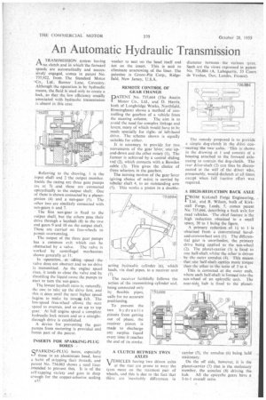
Referring to the drawing, 1 is the input shaft and 2 the Output member. Inside the casing are three gear pumps (a3 at 3) and these are connected epicyclically to the output shaft. One of them is shown connected by a planetpinion (4) and a • sun-gear (5). The other two arc similarly connected with sun-gears 6 and 7.
' The first sun-gear is fixed to the output shaft, but the others pass their drive through a layshaft (8) to the two end gears 9 and 10 on the output shaft: These are carried on free-wheels to permit overrunning.
The output of the three gear pumps has a common exit which can be obstructed by a valve. The valve is worked by centrifugal mechanism shown generally at 11.
In -operation,, at idling speed the valve does not obstruct and so no drive is transmitted. As the engine speed rises, it tends to close the valve and by throttling the liquid cause the pumps to start to turn the sun-gears.
The lowest layshaft ratio is, naturally, the one to take up the drive first, and this it does until the next higher speed begins to make its torque felt. The low-speed free-Wheel allows the next speed to overrun, and so on up to top gear. At full engine speed a complete hydraulic lock occurs and so a straightthrough drive is established.
A device for preventing the gear pumps from motoring is provided and forms part of the patent.
INSERTS FOR SPARKING-PLUG BORES
RPARKING-PLUG bores, especially those in an aluminium head, have a habit of stripping their threads, and patent No. 734,063 shows a steel liner intended to prevent this. It is of the self-tapping variety and goes in deep crough for the copper-asbestos sealing na2
washer to seat on the head itself and not on the insert. This is said to eliminate unscrewing of the liner. The patentee is Groov-Pin Corp., Ridgefield, New Jersey, U.S.A.
REMOTE CONTROL OF GEAR CHANGE
PATENT No. 735,664 (The Austin I Motor Co., Ltd., and D. Harris, both of Longbridge Works, Northfield, Birmingham) shows a methodof controlling the gearbox of a vehicle from
the steering column. The aim is to avoid the need for complex linkage and levers, many of which would have to be made specially for rightor left-hand drive. The scheme shown is equally suitable for either.
It is necessary to provide for two movements of the gear lever; one up-' and-down and the other rotary (I). The former is achieved by a central sliding rod (2), which connects with a Bowden cable (3). This gives the choice of three selectors in the gearbox.
The turning motion of the gear lever (giving choice of ratio) is carried by tubular shaft 4, to an outstanding arm (5). This works a piston in a double
acting hydraulic cylinder (6), which leads, via dual pipes, to a receiver unit (7).
. The receiver faithfully follows the action of the transmitting cylinder and, being connected only by flexible pipes, calls for no accurate positioning.
To prevent the two hydraulic pistons from getting out of phase, the receiver piston is made to discharge any surplus liquid every time it reaches the end of its stroke.
A CLUTCH BETWEEN TWIN AXLES
VEHICLES having two driven axles at the rear are prone to wear the tyres more on the rearmost pair of wheels, and this is due to the fact that there are 'inevitably differences 1n diameter between the various tyres. Such are the views expressed in patent No. 736,884 (A. Labeguerie, 33 Cours de Verdun, Das, Laades. France).
The remedy proposed is to provide a simple dog-clutch in the drive connecting the two axles. This is shown in the drawing at I and consists of a housing attached to the forward axlecasing to contain the dog-chit-ch. The rear drive-shaft (2) can thus be disconnected at the will of the driver who, presumahly, would declutch at all times except when full tractive effort was required.
A HIGH-REDUCTION BACK AXLE CROM Kirkstall Forge Engineering,
Ltd.. and R. Wilson, both of Kirkstall Forge, Leeds, 5, comes patent No. 735,666, describing a back axle for road vehicles. The chief feature is the high reduction obtained in a small space, 30 to 1 being the figure.
A primary reduction of I+ to 1 is obtained from a conventional beveland-crownwhecl unit (1). The differential gear is unorthodox, the primary drive being applied to the sun-wheel (2). The planet-carrier (3) is fixed to one half-shaft whilst the other is driven by the outer annulus (4). This means that.one half-shaft-carries more torque than the other in the ratio of 3 to 4.
This is corrected at the outer ends, where each half-shaft is formed into the sun-wheel of an epicyclic unit. The near-side. hub is fixed to the planet
carrier (5), the annulus (6) being held stationary.
On the off side, however, it is the planet-carrier (7) that is the stationary member, the annulus (8) driving the
hub. All the epicyclic gears have a 3-to-1 overall ratio.