


A Compression-operated Injection Pump
Page 60
If you've noticed an error in this article please click here to report it so we can fix it.
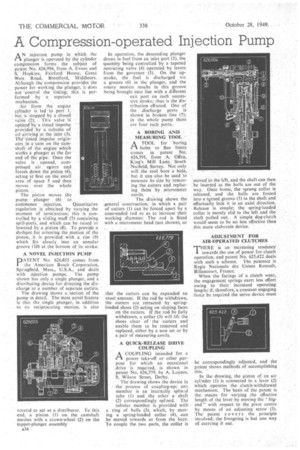
AN injection pump in which the plunger is operated by the cylinder compression forms the subject of patent No. 626,994. from A. Evans and S. Hopkins, Fairford House, Great West Road, Brentford, Middlesex. Although the compression provides the power for Working the plunger, it does not :control the fining; this is performed by .a sepal-ate Mechanism.
Aii. from the engine cylinder iS led to port but. is'stopped by a closed • valve (2): This valve is oPtheif by a timed impulse provided' by a column of oil-ai-rivitg• at the inlet (3). Thef'tinied impulse originates in a cam on the camshaft of the enginewhich Wotts a plunger at the far end of-The tripe.Once the valve is • Opened, compressed -air esters arid forces down the piston (4), acting at first on the small area. Of space 5 and then Moves over the whole
piston. . . .
The piston moves the pump • plunger(6) • to commence injection. Quantitative regulation is: obtained by. varying the moment of termination; this is controlled by a sliding inuff (7) containing spill-ports„ and ,which can be raised or lowered by a pinion (8). To provide a dashpot for arresting the ,motion of.the piston, it is provided, with a. rim. (9) which fits closely, into an annular groove (10) at the bottom outs stroke.
A NOVEL INJECTION PUMP
DATENT No. 626,855 comes from the American Bosch Corporation, Springfield, .Mass., U.S.A., and deals with injection pumps. The pump shown has only a single plunger, and a distributing device for directing the discharge td a number of separate outlets: The drawing shows a section of the pump in detail. The Most novel feature is that the single plunger, in addition to its reciprocating motion, is also
rotated to act asa distributor. To this end, a pinion (1) on the camshaft meshes with a crown-wheel (2) on the tappet-plunger assembly A34 In operation, the descending plunger draws in fuel from an inlet port (3), the quantity being controlled by a tapered restricting valve (4) operated by levers from the governor (5). On the upstroke, the fuel is discharged via a groove (6) in the plunger, and the rotary motion results in this groove being brought into line with a different exit port on each successive stroke; thus is the distribution effected. One of the discharge Ports is shown in broken line (7); in the. whole pump there are four such ports.
A BORING AND MEASURING TOOL
ATOOL for boring holes to fine limits comes in 'patent No. 626,591, from A. Offen, King's MillLane, South Nuffield, Surrey. Not only will the .tool bore. a hole, but it can•also.be used to measure its size by removing the cutters and replacing them by micrometer
anvils. , The drawing shows the
• general construction,in which a pair of cutters (I) can be forced apart by a cone-ended rod so as to increase their
• working diameter. The rod is fitted with a micrometer head (not shown), so that the cutters can be expanded an exact amount. If the rod be withdrawn, the cutters are retracted by springloaded shoes (2) acting on sloping faces on the cutters. If the rod be fully withdrawn, a collar (3) will lift the shoes clear of the cutters and enable them to be removed and replaced, either by a new set or by a pair of measuring anvils.
A QUICK-RELEASE DRIVE COUPLING •
A COUPLING intended for a
power take-off or other purpose for which an occasional drive is required, is shown in patent No. 626,779, by A. Loynes, 9, Wilson Street, Derby.
The drawing shows the device in the process of coupling-up; one. member is an internally splin.A tube (1) and the other a shaft (2) correspondingly splined. The tubular member is provided with a ring of balls (3), which, by moving a spring-loaded collar (4), •can be moved towards or from the bore. To couple the two parts, the collar is moved to the left, and the shaft can then be inserted as the balls are out of the way. Once home, the sprung collar is released, and the balls are forced into a turned groove (5) in the shaft and effectually lock it in an axial direction. Release is simple; the spring-loaded collar is merely slid to the left and the shaft pulled out. A simple dog-clutch would seem to be no less effective than this more elaborate device.
ADJUSTMENT FOR AIR-OPERATED CLUTCHES THERE is an • increasing tendency I towards the use of power for clutch operation, and patent No. 625,422 deals with such a scheme. The patentee is Regie Nationale des Usines Renault, Billancourt, France.
When the facings of a clutch wear, the engagement springs exert less effort owing to their, increased operating length.; if,. therefore, a constant engaging force be required the servo device must be correspondingly adjusted, and the patent shows methods of accomplishing this.
In the drawing, the piston of an air cylinder (1) is connected to a lever (2) which operates the clutch-withdrawal mechanism. The basis of the patent is the means for varying the effective length of the lever by moving the " bigend " with respect to the pivot centre by means of an adjusting screw (3). The patent covers the principle involved; the foregoing is but one way of carrying it out.