 1
1 2
2 3
3 4
4 5
5 6
6 7
7 8
8 9
9 10
10 11
11 12
12 13
13 14
14 15
15 16
16 17
17 18
18 19
19 20
20 21
21 22
22 23
23 24
24 25
25 26
26 27
27 28
28 29
29 30
30 31
31 32
32 33
33 34
34 35
35 36
36 37
37 38
38 39
39 40
40 41
41 42
42 43
43 44
44 45
45 46
46 47
47 48
48 49
49 50
50 51
51 52
52 53
53 54
54 55
55 56
56 57
57 58
58 59
59 60
60 61
61 62
62 63
63 64
64 65
65 66
66 67
67 68
68 69
69 70
70 71
71 72
72 73
73 74
74 75
75 76
76 77
77 78
78 79
79 80
80 81
81 82
82 83
83 84
84 85
85 86
86 87
87 88
88 89
89 90
90 91
91 92
92 93
93 94
94 95
95 96
96 97
97 98
98 99
99 100
100 101
101 102
102 103
103 104
104 105
105 106
106 107
107 108
108 109
109 110
110 111
111 112
112 113
113 114
114 115
115 116
116 117
117 118
118 119
119 120
120 121
121 122
122 123
123 124
124 125
125 126
126 127
127 128
128 129
129 130
130 131
131 132
132 133
133 134
134 135
135 136
136 137
137 138
138 139
139 140
140 141
141 142
142 143
143 144
144 145
145 146
146 147
147 148
148 149
149 150
150 151
151 152
152 153
153 154
154 155
155 156
156 157
157 158
158 159
159 160
160 161
161 162
162 163
163 164
164 165
165 166
166 167
167 168
168 169
169 170
170 171
171 172
172 173
173 174
174 175
175 176
176 177
177 178
178 179
179 180
180 A NEW TROLLEY-BUS
Page 94
Page 95
If you've noticed an error in this article please click here to report it so we can fix it.
Capable of Self-propulsion
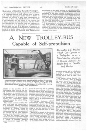
f\NE of the novelties of the 1.,_./Glasgow Show will be the new T.S. petrol-electric trolley-bus, which will be shown in chassis form with a temporary tower to carry the two booms. The basis of the machine is the well-known T.S. petrol-electric chassis, the transmission system being, of course, the patent TillingStevens design.
The control position is of the forward type, and the chassis has a 16-ft. wheelbase. Behind the engine is the controller gear ; the electrical equipment is suitably wound to enable the motor to be driven by current generated by the dynamo of the chassis or by that received directly from the overhead wires.
It will be realized that this vehicle possesses marked advantages over the ordinary trolley-bus, which, of course, is rendered immobile should its current supply fail. Tilt c36 new T.S. model can run as a trolleybus over the ordinary routes, and serve extensions as a petrol-electric machine, or it can turn around at the terminal points without the need for a large open space or special wiring systems ; thus, it should enable the capital cost of a trolley-bus scheme to be reduced.
In certain instances ' abroad trolley-buses cannot operate over level-crossings, because the railway companies prohibit the use of overhead wires across their tracks.• The scope of the new machine is, therefore, a very large one, both at home and abroad.
Reverting to details of the chassis, the engine installed in the machine which we inspected was of 36.15 h.p. R.A.C. rating, developing 95 b.h.p. It is the well-known T.S. four-cylindered power unit, having a bore of 41 ins, and a stroke of 11 ins. In eases
where the engine will be called upon to propel a vehicle only for short distances or over level surfaces, a smaller engine can be used with economy.
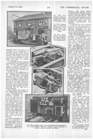
The engine drives directly the the main dynamo. Next in line is the motor, which is wound for 550 volts, so that it can operate off overhead cables when functioning as a trolley-bus. There is a changeover controller which has four positions. One permits the engine to be started by the power obtained from the overhead wires ; this is brought into action during the last stage of the run as a trolley-bus. The second position isolates the master controller and the vehicle functions as a petrol-electric bus. The third position gives neutral, whilst the fourth allows the vehicle to operate entirely as a trolley-bus, and the main dynamo is cut out.
The foot-operated master• controller takes the place of the clutch pedal on a conventional chassis. This and the brake pedal are used
for trolley-bus work. For petrolelectric drive, only the accelerator and brake pedals are needed ; never more than two• pedals are required at any one time. Servo-operated four-wheel brakes are employed. When the engine is running the required suction is obtained from the
induction pipe, but when it is working as a trolley-bus a separate electric motor drives an exhauster which creates the suction. The change-over from one system tot another is automatic and does not depend upon the driver.
A separate electric-lighting dynamo, of C.A.V. manufacture and of the constant-voltage type, is driven through a flexible coupling from the forward end of the armature of the main motor.
Owing to the operation in this country of the 9i-ton limit for double-saloon passenger vehicles, the new T.S. model, as in the case of other trolleybuses, is limited to single-deck service, as it is only of the two.. axle type. In other countries, however, where weight restrictions are less onerous, the new machine can be used as a double-decker.
When laden, the height of the frame above the ground is 2 ft., whilst the overall
length (excluding the starting handle) is 25 ft. 6 ins:, and the overall width 7 ft. 14 in. The front track is 6 ft. 1 in., and the rear track 5 ft. 9 Ins. In other respects this vehicle follows the general specification of the wellknown T.S. petrol-electric machine. he front tyres are 36 ins. by 8 Ins, whilst the dual rear tyres are 34 ins. by 7 ins.
It may be remembered that we described in our issue dated September 16th; 1924, a vehicle embodying similar general principles, which was built by T. S.
Motors, Ltd. (then styled Tilling-Stevens Motors, Ltd.), of Maidstone, for the, Tees-side Railless Traction Board. The new model incorporates an upto-date chassis, which is of the low-loading type, and the braking arrangements are different.
It will not be out of place to recall to the memories of some of our readers the outstanding features of the TS 17a petrol-electric chassis which forms the basis of the vehicle just described.
The four-cylindered engine develops a maximum of 95 b.h.p. at 2,000 r.p.m. The cylinders are of the monobloc type with detachable heads cast in pairs. The crankshaft runs in three white-metallined phosphor-bronze bearings. The camshaft is driven by a helical spur gear with an adjustable idler wheel. Lubrication is by gear-type pump driven from the camshaft. The valves are mounted side by side, the tappets being accessible from the near side. As the vehicle has forward control all the accessories have been grouped on the near side, but the lighting dynamo, as already pointed .out, is coupled up with the transmission system.
The magneto is mounted laterally, so that it can be inspected with ease ; by removing a saddle the complete instrument can be detached in a moment. Carburation is by a Zenith instrument.
Fabric-disc joints couple the engine and propulsion dynamo, Hardy-Spicer joints being employed for the propeller shaft from the motor to the underslung worm-type rear axle. The half shafts are fully floating and the differential can be removed without taking off the road wheels.
No centre bolts are used in the semielliptic springs ; special clips register with the spring pads on the axles. Taper-roller bearings carry the hubs, to which are bolted the disc wheels. The steering set is of the worm and sector variety. The wheelbase is 16 ft., and the minimum ground clearance 5* ins. The turning circle is 60 ft. and the body space (dash to end of frame) 21 ft.
In.
The example which we photographed had a low-level frame end.