 1
1 2
2 3
3 4
4 5
5 6
6 7
7 8
8 9
9 10
10 11
11 12
12 13
13 14
14 15
15 16
16 17
17 18
18 19
19 20
20 21
21 22
22 23
23 24
24 25
25 26
26 27
27 28
28 29
29 30
30 31
31 32
32 33
33 34
34 35
35 36
36 37
37 38
38 39
39 40
40 41
41 42
42 43
43 44
44 45
45 46
46 47
47 48
48 49
49 50
50 51
51 52
52 53
53 54
54 55
55 56
56 57
57 58
58 59
59 60
60 61
61 62
62 63
63 64
64 65
65 66
66 67
67 68
68 69
69 70
70 71
71 72
72 73
73 74
74 75
75 76
76 77
77 78
78 79
79 80
80 81
81 82
82 83
83 84
84 85
85 86
86 87
87 88
88 89
89 90
90 91
91 92
92 93
93 94
94 95
95 96
96 97
97 98
98 99
99 100
100 101
101 102
102 103
103 104
104 105
105 106
106 107
107 108
108 109
109 110
110 111
111 112
112 113
113 114
114 115
115 116
116 117
117 118
118 119
119 120
120 121
121 122
122 123
123 124
124 125
125 126
126 127
127 128
128 129
129 130
130 131
131 132
132 133
133 134
134 135
135 136
136 137
137 138
138 139
139 140
140 141
141 142
142 143
143 144
144 145
145 146
146 147
147 148
148 149
149 150
150 151
151 152
152 153
153 154
154 155
155 156
156 157
157 158
158 159
159 160
160 161
161 162
162 163
163 164
164 165
165 166
166 167
167 168
168 169
169 170
170 171
171 172
172 173
173 174
174 175
175 176
176 177
177 178
178 179
179 180
180 MAKING DROP FORGINGS
Page 90
Page 91
Page 92
If you've noticed an error in this article please click here to report it so we can fix it.
on an Extensive Scale
How a Well-known Coventry Concern Produces Many Classes of Forging ,• a Fully Illustrated Description of the Activities of Thomas Smith's Stamping Works, Ltd.
IN describing the process of forging components in metal N'vhile hot and in dies we prefer to use the words drop forging rather than stamping. The two vords are often used somewhat loosely for the former process, but stamping means to most metal workers he cutting out or forming of articles while cold, whilst lrop forging can have but one meaning.
Drop forgings play an extremely important part in he manufacture of motor vehicles, as without this • apil and economical process such parts as axles, stub tatls,itonnecting rods, etc., could be produced only at a high cost. In outlining this process we have selected one of the best-equipped factories entirely set out for the work, that of Thomas Smith's Stamping Works, Ltd., of Coventry.
Before describing the methods employed we may as well point out that, no matter how complicated the shape of the component to be produced, welding forms no part of the process as carried on in these works.
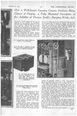
To those who are not familiar with the operation, it is necessary exactly to know what the dies are like and how they are produced. Our illustration No. 3 is of a pair of dies for the production of a stub end, jaw and steering arm in one piece. Some idea of the masnve block of steel necessary can be formed from the fact that the lower is II ins. deep. Years ago such dies 'were made from iron with a facing of hardening steel welded to it, but for modern requirements it has been found necessary to form the block entirely of the same steel throughout.
The block that is to form a die is heat-treated to produce a degree of hardness which will just enable it to be machined with modern tool-steel cutters, so that after the impression is tut in the face of the c32
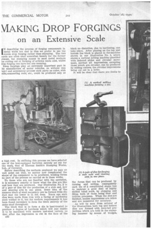
block no distortion, due to hardening, can take place. After planing on the top and bottom the block is placed in the machine shown in our illustration No. 1, which shows a vertical milling machine provided with indexed slides and circular movement, sck-that all impressions, excepting those which are circular, can be produced by milling cutters, the circular impressions being cut out in a lathe.
It will be clear that there are limits to the forms that can be produced by turning and milling, consequently . each die of a complicated shape has to undergo a good deal of highly skilled hand work, by chipping and filing, both of these being slow and tedious processes. When the dies are finished, leaden impressions are taken and are measured for accuracy.
As will he seen from several of the illustrations, both top and bottom dies are formed with dove-tail projections which are held in the stamping hammer by means , of wedges. Extremely careful setting of the dies in relation to one another is necessary, otherwise the component produced would not be perfect. This is done by placing some stiff clay between the dies, then bringing them together and examining the clay to see in which direction some slight adjustment is needed to ensure their being opposite one another.
Before describing the actual forging operation it may he as well to mention the various kinds of hammer that are used. For general work of not too heavy 'a class, the stamp shown in our ill vstration No. 2 is frequently used. This is known as a board hammer; its weighty hammer, or "tup," is raised by means of boards—in this case three in number—which are attached to the tup and extend upwards, passing between two plainsurfaced rollers.
These rollers rotate continuously, their shafts carrying heavy flywheels. They normally stand some distance apart, so that they' do not contact with the boards, but when the tup has to be raised one of the rollers is brought so near to the other that the board is gripped. In this way the tup is raised to whatever height the operator requires; the rollers are then allowed to release the board and the hammer drops. By this means the Operator can produce light or heavy blows.
For heavy forgings the class of stamp shown in illustration No. 4 is employed, the lifting of the tup being caused by a flexible metal belt being brought into contact with a rotating pulley; the hammer is dropped by freeing the belt from contact with the pulley.
In some instances an ordinary steam hammer is used, whilst for " upsetting" a billet to increase its section an hydraulic press is used. The hammer shown in illustration No. 2 has a tup weighing two tons, whilst that depicted in No. 4 weighs five tons: The billets from which the forgings are made are usually of square section, it being known that in all forging work a square section is less likely to develop internal flaws than is a round section. Although a pair of dies will produce a component from a mass of metal, the surplus metal being driven out in a thin, film—known as flash—between the faces of the dies, it is necessary roughly to fashion the article as shown in illustration No. 8; this represents a square billet that has been forged approximately to the shape shown preparatory tb its being placed in the dies which will form it into a connecting rod.
The reduced part shown on the end is shaped so that the metal can conveniently be held in tongs and remains on the forging until it is completed, when it is cut off. As it is necessary to give more than one blow to produce the finished forging the operator must have hold of the metal until the operations are completed.
In illustration No. 3 the parts marked A A show c33 the recess for the stem by which the forging can be held. In some instances the rough fashioning is done by part of the die itself, as shown in illustration No. 5, where what is known as a dummy will be seen on the left-hand side of the die, the metal being placed in this part of the die and turned over on its side, receiving sufficient blows to reduce it to approximately the dimension that will fill the die, allowing for a certain amount' to spew out to form the flash.
While the forging is receiving the necessary number of blows a constant blast of compressed air is directed on to the dies in order to remove all scale and to keep them cool. Oil is also applied to preserve the surface of the dies.
When each forging is finished It is surrounded by a flash which varies in thickness from dn. to A in. To remove this, a clipping bed is made through which there is an opening exactly corresponding with the outline of the component. This forms 'the bottom, or cutting, tool, whilst the upper tool, or punch, is of such a shape that it will, without distorting the article, force it through the cutting tool; by this means the flash is sheared off.
Flaws in forgings may arise from many causes; a defect may exist in the billet, or what 'is known as a "run" may have taken place in the forging operation. This is an overlapping of the metal during forging, and as such steels as those used in motor construction are not forged at a welding heat, no uniting of the metal takes place, although it may be so closely compressed that the defect •is hard to detect. In the Thomas Smith's Stamping Works a specially trained set of men is employed to examine all forgings for defects. These operatives know exactly where flaws are likely to be found, although manysuch defects, when discovered, would be invisible to the casual observer. The bulk of the forgings produced in these works are either normalized or heat-treated, according to3tile steel of which they are composed and the work for which they are destined. For this purpose the forgings are laid on long trays and slid into furnaces which are regulated for temperature by pyrometers ; these enable the progress of the heating carefully tohe checked. After the heat treatment the forgings, are examined for distortion and are tried against templates or ot her measuring means, as in such cases where jig-drilling of bosses has to be performed it is essential that the forging should be eg.actIy the shape required, otherwise holes drilled in them wOuld not be central with the bosses.
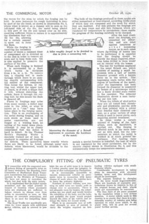
The test for hardness employed is the usual Brinell one, which consists of making a small
pression with a ball of known diameter pressed with a known force on to the -article. The impression made varies with the degree Of hardness of the metal. After the impression has been formed its ,diameter is measured by 'beans of a microscope which has a finely divided scale, visible to the operator.. The adjacent illustration shows a man carrying out this test.
When the billets of steel arrive they are all tested both chemically and physically, and the ends are then painted with a colour that denotes their chemical content, as a great variety of alloy steels is used in motor parts, each requiring special treatment.
In these works a certain amount of forging of the light alloys, such as duralumin, is carried out. The forging is effected much in the same manner as with steel, but the temperature at which the metal is werked is of much greateeimportance. For heating ' these metals a special furnace is installed, the heat of which is not regulated by the usual pyrometer, but by the electric control shown in illustration No. 6, and this automatically keeps the temperature constant.