


SPRINGING WITHOUT SPRINGS.
Page 24
If you've noticed an error in this article please click here to report it so we can fix it.
A Résumé of Recently Published Patent Specifications.
1:Trider the above title we briefly described, on page 22 of our issue of February 27th, of this year, a springing system patented by Mr. F. W. Lanchester, the outstanding feature of which was that the inventor dispensed entirely with springs, depending solely for shock.
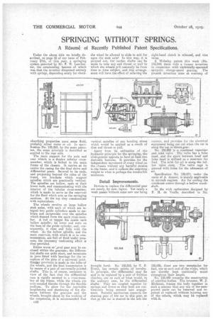
absorbing properties upon some fluid, probably either water or oil. In specification No.' 132,363, by the Game patentee, the same principle is described as applied to the rear axle.
The main support for the axle and rear wheels is a duplex tubular crossmember, which is bolted to the main frame of the chassis. It carries at its centre the casing for the final drive and differential gears. Secured to its ends, and projecting beyond the sides of the frame, are brackets which support spindles which are practically vertical. The spindles are hollow, open at their lower ends, and communicating with the interior of the tubular dross-member, which is made to serve as the reservoir for the fluid which acts as the springing medium. At the top they communicate with replenishers. .
The wheels revolve on large hallow stub axles, with each of which are integral two guide cylinders made to embrace and reciprocate over the spindles which depend from the main cross-member. A rod or tappet fits inside each hollow spindle; its lower end rests on the base of the snide cylinder, and, consequently, it rises and falls with the wheel. As the hollow spindle, and the main reservoir, with which it is in communication, are full of fluid 'Under pressure, the necessary cushioning effect is thus provided.
Either worm or raevel gear may be enclosed within the geareasea the differential shafts are quite short, and terminate in jaws fitted with bearings for the reception of the pins of a universal joint. Similar provision is made in the hubs of the wheels, and the final transmission is by means of a pair of universally-jointed shafts. This is, of course, necessary in view of the fact that the differential case is rigidly secured to a cross-member of the frame, while the wheels are only coupled thereto through the flexible medium. To allow for the inevitable lengthening and shortening of the distance between the ,gearease and the wheels, brought about by the working of the suspension, it is recommended that
c42
the wheel be allowed to slide to and fro upon the stub axle! In this way, it is pointed out, the cardan shafts can be made to take any end thrust or pull to which the wheels ill naturally be from time to time subject, and this arrangement will have the effect of relieving the vertical spindles of any bending stress which would be applied as a result of that end thrust OT.
Apart from its utilization of the hydraulic principle for the springing, the arrangement appears to have at least two desirable features. It provides for the independent movement of every wheel on the chassis without any harmful strains to the frame, and it reduces the unsprung weight to what is perhaps the irreducible mirumum.
Detail Improvements.
Devices to replace the differential gear are surely, by new, legion. Yet rarely a week passes without some new one being
brought forth. No '132,318, by T. F. Evans, has certain points of novelty. In principle, the differential may he said to be replaced by a pair of friction clutches, one on each of what would, in the ordinary case, be the differential shafts. They are coupled together by springs and levers so that both are continuously being pressed into engagement. Suitable mechanism connects the steering gear of the car to this gear, so that as the ear is steered to the left the
right-hand clutch is released, and vice versa.
A Wolseley patent this week (No. 132,349) deals with a former invention in connection with eleotricially-operated • epicyclic change-speed gearing. The present invention aimsat ecenoiny of
current, and provides for the electrical equipment being cut out when the car is using the top or direetegear. No. 132,093 is a combined vaporizer and inlet valve. The valve has a false head, and the space between head and false head is utilized as a reservoir for fuel. The inlet for oil is along the hollow valve stem. The valve cage is pierced with holes for the admission of air.
Specification N. 132,071, under the name of A. Anzani, is mainly applicable to aircraft engines. Air for cooling the crankcase enters through a hollow crankshaft.
In the wick carburetter designed by F. B. de Veulle, described in No.
132,439, there are two receptacles for fuel, one at each end of the wicks, which are thereby kept Continually moist throughout their length.
No. 132,459 concerns the construction of omnibus bodies. The inventor, W. J. Hickman, frames the body together in such a -manner that any one of the component parts can be removed and repaired or replaced without injuring any of the others, whioh may be replaced with it.