


Lights: right and bright
Page 28
Page 29
Page 30
If you've noticed an error in this article please click here to report it so we can fix it.
How to check your lights and lighting circuits and diagnose faults speedily
THE PUBLIC DEBATE about making the use of headlights compulsory at night in urban areas has focused attent:on on headlamp adjustment, and the coming of the dark evenings has revealed the annual crop of "one-eyed vehicles" creating their own sort of danger.
Putting electrical systems into a good state and keeping them there has often been surrounded with an aura of mystery, but while there are certainly jobs which need the skilled hand of the auto-electrician or the specialist agent, some of the important basic checks are mainly a matter of knowing the correct procedures and understanding what the readings mean.
So we asked the technical service department of Joseph Lucas (Sales and Service) Ltd, to whom all things electrical are meat and drink, to set down their checking procedures for our readers. We'll be running these practical articles at monthly intervals, and graduating into eleetrics for the heavier end of the market ; but this first instalment concentrates on lights and lighting, batteries and direction indicators—with special emphasis on light commercials.
Faulty lighting performance is most commonly the result of the simplest failure or neglect. As well as being sound safety sense, it is also a legal requirement for the lamps fitted to a vehicle to be maintained in good optical and mechanical condition—and this legal obligation applies equally • when the vehicle is in use on the road in daytime as well as at night.
So it is of paramount importance that lenses a n d reflectors are clean and in a serviceable condition, and that the bulbs are of the correct wattage.
In particular, the following lamps, which are specifically required by law, and are known as "obligatory lamps" should be checked periodically : (a) Headlamps.
(b) Side, rear and number plate lamps. (e) Direction indicator lamps. (d) Stop lamps.
Check whether each lamp lights when it is switched on. If it does not, it is probably due to a faulty bulb, which should be checked by substitution. If, however, the bulb is satisfactory but the lamp does not light up, check for an opencircuit either in the insulated line or earth line. If the lamp lights up, but not at full brilliance, there is probably a faulty earth connection or a high resistance in the wiring. In either case, a systematic pointto-point check of the wiring circuit is necessary. The "volt drop " or "voltage loss " method is especially recommended for locating faults. First, check the supply voltage at the battery, while the lamp is switched on. Then, check the voltage at the lamp itself. If the difference between these two readings (the volt drop or loss) is more than 10 per cent of the battery voltage, then there is a fault in the circuit, either in the insulated line or the earth line. A point-to-point check should then be carried out to locate the fault.
An ammeter is also required when checking the direction indicator lamps. This is because the rate of flash varies with the current consumption of the flasher .unit and the law states that lamps should flash between 60 and 120 times a minute.
There are many different lighting circuits in use. Those shown in the following tests are typical only.
Test equipment
The following items of test equipment are required Hydrometer Voltmeter (scale 0-20V) Preferably industrial grade meter.
Ammeter (scale 5-0-20A) Preferably industrial grade meter.
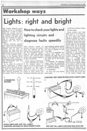
1. Battery, First, check the batter connections. Ensure they are clean and tight. Then, use the hydrometer to ascertain the state of battery charge. All cell readings should be approximately the same (within 40 ' points), and should not be less than 1.230, indicating that the battery is at least 70 per cent charged. If the readings are 5 STOP LAMPS: CHECKING lower, the battery should be re-charged by means of a battery charger.
Ideally, the battery should be recharged at a rate equivalent to 10 per cent of its specified capacity. For instance, if the battery is rated at 40Ah then the ideal charge rate is 4Ah. When boost charging, ensure that a battery thermostat is used to prevent overheating and possible permanent battery damage. Trickle charging is quite acceptable though compared to the other methods it takes longer. The trickle charge rate is normally about 2.5 per cent of the battery's specified output.
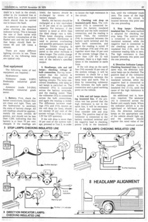
2. Headlamps, side and tail lamps ; checking voltage at bulb connection. Having ascertained that the battery is sufficiently charged, test the lighting circuits. The lamp concerned (headlamp, side lamp or tail lamp) is switched on. The voltmeter (VI) is connected across the battery terminals, and the reading noted. Then the voltmeter (V2) is connected across the bulb connections, and again the reading is noted. The difference between readings (V1) and (V2), known as the volt drop (or loss), should not exceed 10 per cent of the system voltage. (That is to say, 1.2V for 12V systems).
If the volt drop is more than 10 per cent of the system voltage, proceed to Test 3, in order
INSULATED LINE
to locate the high resistance in the circuit.
3. Checking volt drop on insulated-earth lines. The voltmeter (V3) is connected between the battery insulated terminal and the bulb insulated connection, and the reading is noted. Then, the voltmeter (V4) is connected between the battery earth terminal and the bulb earth connection, and again the reading is noted. If the readings (V3) and (V4) are together more than 10 per cent of the system voltage (that is, more than 1.2V for 12 volt systems), there is a high resistance in the insulated or earth lines.
If the volt drop on the earth line (V4) exceeds 10 per cent of the system voltage, it will be necessary to check for a bad earth connection between the lamp body and earth. This is done by connecting voltmeter (V5) between the bulb earth connection and a good earthing point on the vehicle.
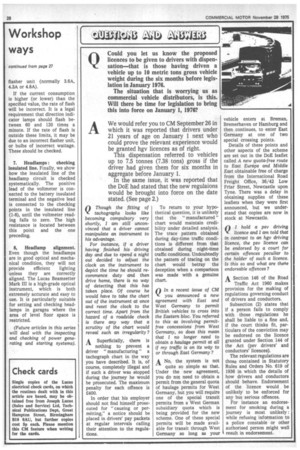
4. Side and tail lamps checking insulated line. If the previous test has proved that the high resistance is not in the earth line, it will be necessary to check the insulated line. First consider side and stop lamps. The positive lead of the voltmeter is connected to the battery insulated terminal and the negative lead to checking points (1-6) in the insulated line, until the voltmeter reads zero. The cause of the high resistance in the circuit is located between this point and the one preceding.
5. Stop lamps : Checking insulated line. The same method is adopted for checking the stop lamp. The positive lead is connected to the battery insulated terminal, while the negative lead is connected to the checking points in the insulated line (1-9), until the voltmeter reading falls to zero. The high resistance is then located between this point and the one preceding.
6. Direction Indicator Lamps: Checking Insulated Line. In the same way, the direction indicator lamp can be checked. The positive lead of the voltmeter is connected to the battery insulated terminal, while the negative lead is connected to the checking points in the insulated line (1-11), until the cause of the high resistance is discovered.
An additional test is, however. required. The ammeter (A) is connected across the flasher unit supply leads. When the indicator switch is in the right-hand or left-hand position, the direction indicator lamps on the appropriate side of the vehicle should light up, and the ammeter should register the rated value of the flasher unit (normally 3.6A, 4.3A or 4.8A).
If the current consumption is higher (or lower) than the specified value, the rate of flash will be incorrect. It is a legal requirement that direction indicator lamps should flash between 60 and 120 times a minute. If the rate of flash is outside these limits, it may be due to an incorrect flasher unit, or bulbs of incorrect wattage. These should be checked.
7. Headlamps : checking insulated line. Finally, we show how the insulated line of the headlamp circuit is checked systematically. The positive lead of the voltmeter is connected to the battery insulated terminal and the negative lead is connected to the checking points in the insulated line (1-8), until the voltmeter reading falls to zero. The high resistance is located between this point and the one preceding.
8, Headlamp alignment. Even though the headlamps are in good optical and mechanical condition, they will not provide efficient lighting unless they are correctly aligned. The Lucas Beamsetter Mark III is a high-grade optical instrument, which is both extremely accurate and easy to use. It is particularly suitable for setting and checking headlamps in garages where the area of level floor space is restricted.
(Future articles in this series will deal with the inspecting and checking of power generating and starting systems).