


Isolating Valve for Pneumatic Brake System
Page 36
If you've noticed an error in this article please click here to report it so we can fix it.
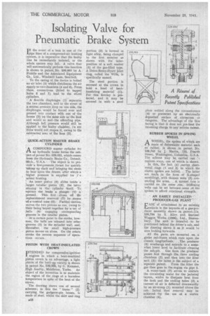
I N the event of a leak in one of the pipe lines of a compressed-air braking -system, it is imperative that the faulty line be immediately isolated, or the -whole system may fail. A valve that will automatically perform this function is shown in patent No. 539,895 by A. Puddle and the Asiociated Equipment Co., Ltd., Windmill Lane, 'Southall.
To the casing of the device is bolted an air inlet (5) which distributes the air supply to twci chambers (4 and 6). From these, connections (fitted to tapped holes 3 and 7) lead to the wLeel ,cylinders.
A flexible diaphragm (1) separates the two chambers, and in the event of a serious pressure drop on one side, the diaphragm would be forced over and pressed into contact with one of the bosses (2) on the same side as the leak and would so seal the offending pipe. -Although full, pressure would still be applied to the faulty chamber, its net force would not reopen it, owing to the subtracted area of the boss (2).
QUICK-ACTION MASTER BRAKE CYLINDER
ACOMPOUND master cylinder for an hydraulic brake forms the subject of patent No. 539,851, which comes from the Hydraulic Brake Co., Detroit, -Mich., U.S.A. The object is to provide a low-pressure ,thrust for quickly taking up slack and bringing the shoes to bear upon the drums, after which a higher pressure is supplied for ,t' e actual braking.
An inner piston (6) slides inside a larger, tubular piston (3), the latter nioying in -the cylinder itself. To .operate the brake a plunger (1) is pressed. This first closes off the replenishment reservoir (7). by means of a conical nose (2). Further-motion moves the two pistons as one, owing to Their -being keyed together by a set of balls (4) engaging corresponding grooves in the smaller pistem.
• , :At a certain point in the stroke, however, the balls are released into other • grooves (5) in the cylinder wall, and, thereafter, the small high-pressure piston moves on alone. On the return stroke the reverse sequence cf operations occurs.
PISTON WITH HEAT-INSULATED CROWN I NTENDED for compression-ignition engines in which a heat-insulated piston crown is an advantage, a light piston of the built-up variety is shown in patent No. 539,568, by G. Kammer, kigh Austby, Middleton, Yorks. An object of the invention is to maintain , the region of the rings at a harmless temperature in spite of the heat of the crown.
The drawing shows one of several schemes; in this the " frame " (2) carrying the gudgeon-pin bosses, is made of steel, whilst the skirt and ring plate welded along the circumference (4) or protected by an electrically deposited surface of chromium or tungsten. The advantage of the thin facing is that it does not pre-licat the incoming charge to any serious extent.
RUBBER SPOKES IN SPRING WHEEL
A WHEEL, the spokes of which are
made of deformable material such as rubber, is shown in patent No. 539,743 by J. Martin, 122, Fourth Street, Washington, .Columbia, U.S.A. The scheme may be carried out '1 various ways, one of which is shown.
In this, the hub (4) .carries sheetmetal rings (1 and 3) to which the elastic spokes are bolted. . The latter are made in the form of X-shaped mouldings, with thinner webs (2). con necting the arms. A normal tyre is carried on the outer rim. Stiffening webs can be set between , some of the spokes to afford rotational strength.
AN EASILY INgrAuttn PRODUCER-GAS' PLANT Eof attachment to an existing hicle is the keynote of a gas-producer assembly shown in patent,-17o. 539,794 by S. Alley and Sentinel Waggon Works (1938); Ltd., Shrewsbury, The unit is intended to •be positioned behind the driver's cab, and the drawing shows it as it would he seen looking forwards,
All the parts are mounted on a girder sub-frame which rests upon the chassis longitudinals. The producer (6) overhangs and extends to a somewhat lower level to facilitate cleaning the ash-pit. Gas from the producer passes first through _the. three cooling chambers (2) an,d then intoth6 filter unit (3); the latter is the subject of a separate patent. From the filter the .gas then goes to the engine via pipe 5.
A water-tank (7) serves to contain the circulating water for the jacketet) tnyere, whilst to dissipate heat from the tank and the cooling tubes (2) a current of air is deflected downwardly by an air-scoop (1) mounted above the cab. Initial dust removal may be achieved -by the use of a vortex chamber (4).