


THE THORNYCROFT GAS• PRODUCER
Page 28
If you've noticed an error in this article please click here to report it so we can fix it.
A Resume of Recently Published Patents.
THE PRINCIVAL difficulty which arises in connection with the use of a gas producer on a motor vehicle is the maintenance of the furnace and fire in a condition to respond to variations in the demand for fuel, particularly in case of a 'temporary stoppage of the engine, when; if special precautions be not taken, there is a risk of the producer getting into such a state that artificial means have to be taken to restore it. Various methods of _preventing this temporary lapse have from time to time been tried, and a novel one is outlined in specification N. 187,022, by John I. Thornycruft and Co., Ltd. It consists in the employment, as part of the producer-gas plea; of an arrangement, including an exhauster, which, whether it be continuously oe.oceasionaily in opera,. . thins, acts only at low loads, when there is a minimum demand for gas on the part of the engine, to withdraw and waste gas from the producer, thus maintaining that degree of suction which is needed to keep the plant in working order.
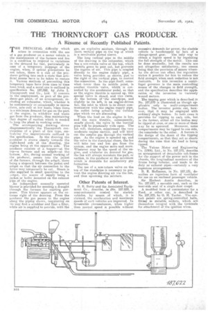
• The accompanying drawing shows diagrammatically the Thernycroft con' straction of a plant of this type, embodying the improvements outlined in the specification. In the drawing the :produeer ehown clearly towards the
right-hand side of the drawing, the engine being at the opposite side. The producer consists of a hopper—at the top—a fereace and an ashpit—at the bottom. Air, during normal working of the producer, passes into the jacket of the furnace, through the asbpit, there being a stopcock between the jacket and .ashpit SO that the air connection to the latter may temporarily be cut. Steam is ' also supplied in small quantities to the estipit, the source of supply being a jacket or boiler mounted on the exhaust pipe, of the engine.
An independent manually operated blower is provided for oreating a draught through the furnace for starting purposes. This blower appears on the extreme right of the drawing. From the producer the gas passes to the engine along the piping shown, negotiating on its way first a scrubber and then a filter, while air is supplied to provide, with the gas, an explosiYe mixture, through the short vertical pipe at the top of which is a revolvable ported sleeve.
The long vertical pipe in the middle of the drawing is the exhauster, which has a non-return valve at the hip, which permits gases to pass out, but prevents the ingress of air. This pipe is coupled directly to the engine supply pipe,. a valve being provided or shown, just to the right of the vertical pipe, to control the connection. In the pipe. itself, somewhat lower than its middle point, is another throttle 'valve, which is controlled by the accelerator pedal, so that as the engine throttle is opened up, this special valve is closed, and vice yersa. At the bottom of the standpipe, and slightly to its left, is an engine-driven fan, the inlet to which ie,iredirect communication with'the erigine supply the outlet being actually the vertical pipe which we are discussing.
When the load on the engine is low, and the main throttle, consequently, rie•arly closed, the valve in the vertical pipe will hoc practically wide open. The fan will, therefore, supplement the very moderate engine suction, and will blow ont the surplus gas through the vertical pipeAs the engine is weeded up, and the valve in the standpipe closes, the fan will take lees arid less gas from the system, am] the engine' moteand.more. Whatever may be the speed of the engine, and whateVer its deinand. for gas, the fan will always maintain the pull, or suction, in the producer at. the minimum which is desirable for satisfactory gas formation.
The use of a note:return valve on the top of the standpipe is necessary to prevent. the engine drawing air via the fan, and thus upsetting the mixture.
Other Patents of Interest.
D. E. Batty and the A.sseciated Equipment Co., describe, !tei elNi:o. 187,059, a semi-automatic control for electric vehicles, by means of which, it is claimed, the acceleration and maximum speeds of such vehicles are improved. In favourable circumstances, when higher than normal speed is possible without excessive demands for power, the electric vehicle is handicapped by lack of a .change-speed gear. The only way to obtain a higher speed is by regulating the full etrength of the motor., •Thie ern be done manually, but the results are not altogether satisfactory, one reason being that the provision of means Whereby the driver can effect the reguiation makes it possible for hint to reduce the field strength when such reduction is not desirable. . In this invention a centrifugal governor is the main controlling means of the changes in field strength, and the specification describes the application et the invention to variously wound motors.
The tipping gear which is described in No. 187,070 is illustrated as though applicable only to multi-compartment bodies. The inventor points out, howeyer, that it may be employed with orddiar;eingle bodies. lii With cases it provides for tipping to each side, but in the former, either all the bodies may be tipped at once, or one or more ef them way be so operated. Moreover, smile compartments may be tipped to one side, the remainder to the other. • A feature is the design of the doors of the tipping compartments, so that they actas shoots during the time that the load is being tipped.
The Vulcan Motor and Engineering Co. (1906), Ltd., in No. 187,171, describe an arrangenient of detachable sub-frame for the suppert of the power unit in the chassis, the longitudinal members of the frame being:tubular, and made to do duty as exhaust pipes—certainly a very ingenious arrangement.
B. E. Hoffmann, in No. 187,131, describes an ingenious form of ventilator for use on an enclosed paasenger vehicle.
Sir Herbert Austin describes, in No. 187,087, a movable seat, such es the near-side seat of a single-door coupe.
A modified form of commutator for Ferd, m other car, is described in N. 187,12.U, by G. H. Taylor. The contactpoints are. spring-controlled balls, fitting in suitable, sockets, which .are themselves integral with the terminals for attachment of the ignition wires.