Patents Completed.
Page 20

If you've noticed an error in this article please click here to report it so we can fix it.
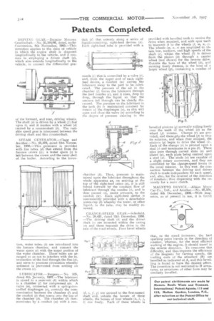
DRIVING GEAR.—Daimler Motoren Gesellschaft.—No. 25,104/06, dated, under Convention, 8th November, 1905.—This invention applies to the class of vehicle in which the engine shaft is disposed longitudinally to the vehicle, and it consists in employing a driven shaft (a), which also extends longitudinally to the vehicle, to connect the differential gear of the forward, and rear, driving wheels. The shaft (a) is driven by a wheel (f) fast upon it, and it meshes with a wheel (d) carried by a countershaft (b). The variable speed gear is interposed between the driving shaft and this countershaft.
STEAM GENERATOR.—Clegg and Another.—No. 25,476, dated 12th November, 1906.—This generator is provided with fire tubes (d) that extend from the furnace crown (c); a water space (e) is left between the crown and the outer shell of the boiler. According to the inven tioi , water tubes (b) are introduced into the furnace chamber, and connect the water space (e) with the upper portion of the water chamber. These tubes are arranged so as not, to interfere with the introduction of the fuel through the flue (a), and serve to promote circulation whereby sediment is prevented from settling on the crown (c).
LUBRICATOR.— Burgess,— No. 525, dated 8th January, 1907.—The lubricant is stored in a reservoir (k) within which is a chamber (1) for compressed air. A valve (a), connected with a spring-controlled diaphragm (a), controls the communication between the chamber (1) and the conduit (t) that opens into the top of the chamber (k). The chamber (k) corn• municates by a conduit (m) with a con duit (d) that extends along a series of liquid-containing, sight-feed devices (a). Each sight-feed tube is provided with a nozzle (c) that is controlled by a valve (c), and, from the upper end of each sightfeed device, a conduit (w) carries the lubricant away to the part to be lubricated. The pressure of the air in the chamber (K) forces the lubricant through the feed nozzles (c), and it rises, drop by drop, through the liquid so that the amount fed through can be clearly discerned. The pressure on the lubricant in the tank (k) is maintained constant by means of the diaphragm (a), as this will open and close the valve (n) according to the degree of pressure existing in the chamber (k). Thus, pressure is maintained upon the lubricant throughout the whole apparatus as, on arriving at the top of the sight-feed tubes (a), it is still forced forward by the constant flow of lubricant through the nozzles (c), and is thus passed on, under pressure, to the conduit (w). Each sight-feed device is conveniently provided with a detachable screw-cap (b) whereby the water, or other liquid, in the tube, may be readily renewed.
CIIANGE-SPEED GEAR.—Schofield. —No, 28,431, dated 13th December, 1906. —The driving shaft (b) and the driven shaft (c) are mounted within the casing (a) and these transmit the drive to the axle of the road wheels. Four bevel wheels (d, e, f, g) are secured to the first-named shaft and, outside the bosses of these wheels, the bosses of four wheels (k, 1, j, k) run freely. Each of these wheels is provided with bevelled teeth to receive the drive when required, and with spur teeth to transmit it to the wheels (I, m, a, 0). The wheels (M , n, 0) are employed to obtain low, medium, and high speeds of the shaft (e), whilst the wheel (I) is driven from the pinion (h) through a carrier wheel (not shown) for the reverse drive. Outside the boss of the wheel (h), and running freely thereon, is the boss of a larger wheel (p), containing a number of bevelled pinions (9) normally rolling freely over the teeth of the wheel (h) as the wheel (p) rotates. Clamps (r) are provided, and these grip the wheel (p) to stop its rotation, and when thus stopped, the pinions (q) begin to drive the wheel (h. Each of the clamps (r) is pivoted upon a stud (s) and terminates in a pin (I). These pins pass through curved slots (v) and plates (u), each plate being centred upon a stud (x). The studs (x) are capable of a slight rotary movement, and they are controlled by the change-speed levers in the usual manner. In this way, the connection between the driving and driven shaft is made independent for each speed, and, also, for the reversal of the direction of rotation ; thus dispensing with the necessity for a main clutch.
MAGNETO DEVICE.—Albion Motor Car Co., Ltd., and Another.—No. 27,570, dated 4th December, 1906.—With magnetos, as at present in use, it is found that, as the speed increases, the best sparking point travels in the direction of rotation, whereas, for the most efficient working of the engine, it should travel in the reverse direction. To overcome this difficulty, and thus improve the efficiency of the magneto for varying speeds, the trailing ends of the armature (B) are bevelled as indicated at A, and this bevelling is found to have the desired effect. The invention is not restricted to H armatures, as armatures of other form may be similarly bevelled.


