


spension, 3
Page 79
If you've noticed an error in this article please click here to report it so we can fix it.
FOUR or six wheels of a ie need to be kept in contact the ground, irrespective of uneven it may be. There are nal ways of achieving this. re simplest of the systems the balance beam, is trated in Figure 1. The rearKling shackle of the forward ng is connected by the beam le swinging shackle at the t end of the rear spring. m the wheel on the foremost negotiates a bump, the ince beam pivots at its centre pushes the rear spring mwards so that the load is alised.
a previous article it was said , because of torque reaction, iring is subject to a twisting on when the vehicle is alerating. In the swinging m type bogie, the forward rig will tend to move unwards at the rear and the spring will move up at the t.
.cting on the balance beam, h these movements will se a load transfer to the ward axle. As there is now ; weight on the rear axle re will be a tendency, on lies where all four wheels are ten, for the wheels on the r axle to spin.
klthough its feature may not important for a vehicle driven well maintained roads, it is a Iclicap where adhesion is an aortant factor, such as where )uv or ice is encountered or in road situations on site work.
s type of suspension is erred to as "re-active".
he balance beam cannot be
made over-long without making the distance between axle centres longer than is desirable if tyre scrub is to be avoided. This results in either excessive angular movement of the beam or limitation of axle movement. Again, this is not important for vehicles engaged on normal road work where spring deflection is unlikely to be excessive.
Figure 2 shows the bell crank bogie which overcomes some of these difficulties. In this design the springs are connected to bell crank levers "A" and "B" and a rod "C".
Figure 3 shows a very popular arrangement where twin springs are mounted on a trunnion bearing. This design is particularly suitable for vehicles used on site work or where much time is spent in the off road situation, as a greater degree of movement between the axles is possible. The bottom spring is often replaced by torque bars.
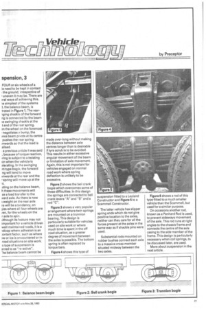
Figure 4 shows this type of suspension fitted to a Leyland Constructor and Figure 5 to a Scammell Constructor.
The latter vehicle has slipper spring ends which do not give positive location to the axles, neither can they care for all the forces present at the axles in the same way as if shackle pins were used.
Substantial rods mounted on rubber bushes connect each axle to a massive cross member situated midway between the two axles. Figure 6 shows a rod of this type fitted to a much smaller vehicle than the Scammell, but used for a similar purpose.
On occasions another rod, known as a Panhard Rod is used, to prevent sideways movement of the axle. This rod runs at right angles to the chassis frame and connects the centre of the axle casing to the side member of the frame. This design is particularly necessary when coil springs, to be discussed later, are used.
More about suspension in the next article.