


Novel Design of Cross-country Vehicle
Page 68
If you've noticed an error in this article please click here to report it so we can fix it.
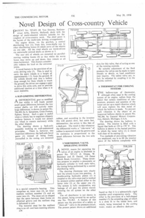
PATENT No. 707,032 (H. Van Doorne, Stationsstraat A54a, Deurne, Holland), deals with the design of multi-wheeled vehicles suitable for the roughest of cross-country work. The chief point is the layout of the multi-axle driving arrangements.
The engine drives, via the gearbox, a central distributing box (1); from this, cross-shafts run to other distributing boxes (2) which serve all the wheels on one side. All the road wheels are worm-driven via universally jointed shafts as shown at 3.
The rear sets of wheels are mounted on parallelmoving rocking beams (4) so that whilst the worm boxes may move up and down, they remain at all times horizontal. This feature considerably reduces the load on the universal joints.
A novel feature is the provision of an extra driving axle (5). This is used to carry the spare wheels at a height of approximately 1 ft. from the ground. If the vehicle should sink into a hollow deep enough for these wheels to touch the ground, the driver can engage a gear to drive this extra axle, and so provide additional traction at a time when it is most desirable.
A SLIP-LIMITING DIFFERENTIAL
A DIFFERENTIAL gear so modified
that -whilst it will freely permit small speed differences between the two output shafts, yet will actively resist large differences, is shown in patent No. 706,989, by A. Sampietra, Great Fosters, Egham, Surrey. Such a gear is useful when a vehicle has to negotiate slippery surfaces because it would not permit one wheel to remain stationary while the other slipped.
The drawing shows a back-axle assembly working on well-understood principles, There is, however, one important difference; the half-axle bevel gears (1) instead of being freely journalled in the casing, are mounted in a special composite bearing. This comprises an inner race (2), an intermediate resilient member (3) and an outer race (4). The races are so shaped that the space between them forms an elliptical groove and the resilient ring is deformed to suit.
The material used for the resilient ring is an oiland heat-resisting silicone A34 rubber, and according to the inventor this will permit slow, but resist fast, deformation; the action is like that of a dash-pot. The result is that whenever the differential works, a " tide-wave" of rubber is squeezed round the groove and its resistance is proportional to the speed difference between the two axle shafts.
UNORTHODOX VALVEOPERATING SYSTEM riA NOVEL means for operating the valves of an engine is disclosed in patent No. 707,131 (I. Owens, W. Brammer and D. Daniel, 110 Outer Marsh Road, Coventry). These inventors propose to employ a pneumatic or hydraulic cylinder to work each valve, the timing being performed by a central distributing valve.
The drawing illustrates very clearly how the scheme is put into practice. A double-acting hydraulic piston (1) is coupled to the valve-stem and is worked by pressure pulses applied either to the lower inlet (2) or the upper one (3). The system is fully recuperative, any leakage of oil past the piston merely entering the oil system on the other side.
The oil distributor is not shown in this patent, being covered by an earlier one No. 701,963. A feature of this patent was the provision of a safety or " blow-off" valve in the pressure circuit. The present patent shows an additional duty for this valve, that of acting as one of the running controls.
By suitable adjustment of the fluid pressure the valves can be made to Open sharply or slowly, as load conditions may require. The safety valve can, in fact, be adjusted by coupling it to the throttle control.
A THERMOSTAT FOR COOLING SYSTEMS
THE bellows-type of thermostat, although often used in the cooling system of an engine, suffers from the defect that certain conditions of temperature, pressure and aeration of the water can set up a rapid vibration which will soon rupture the thin metal of which the bellows is made. To prevent such vibration is the object of an improved bellows shown in patent No. 706,386, by General Motors Corporation, Detroit, Michigan, U.S.A.
The drawing shows the bellows in section. The interior is filled with a liquid that boils at 150 to 170° F. The bellows is shown in the heated position in which the water valve (1) is thrust well clear of its seating (2).
Two methods of preventing vibration are employed; one is to fill the interior space of the bellows completely with liquid so that it is a substantially rigid member until evaporation starts. The other is the provision of a bell-shaped member (3) the extending edge of which is a close fit to the inside bore, and which, being immersed in the cooling water, makes an effective dash-pot.