A High-performance Two-stroke Engine
Page 62

If you've noticed an error in this article please click here to report it so we can fix it.
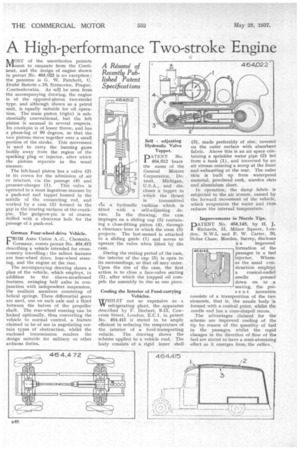
MOST of the unorthodox patents seem to emanate from the Continent, and the design of engine shown in patent No. 4(14,022 is no exception ; the patentee is G. W. Patchett, U. Druh6 Baterie c.10, Stresovice, Prague, Czechoslovakia. As will be seen from the accompanying drawing, the engine is of the opposed-piston two-stroke type, and although shown as a petrol unit, is equally suitable for oil operation. The main piston (right) is substantially conventional, but the left piston is unusual in several respects. Its crankpin is of lesser throw, and has a phase-lag of 90 degrees, so that the two pistons move together over a small portion of the stroke. This movement is used to carry the burning gases bodily away from the region of the sparking plug or injector, after which the pistons separate in the usual manner.
The left-hand piston has a valve (2) in its crown for the admission of air or mixture, via the passage (4) and
pressure-charger (1). This valve is operated in a most ingenious manner by a push-rod and tappet housed in the middle of the connecting rod, and worked by a cam (3) formed in the gap in the bearing surfaces of the crankpin.. The gudgeon-pin is of course, drilled with a clearance hole for the passage of a push-rod.
German Four-wheel-drive Vehicle.
FROM Auto Union A.-.G., Chemnitz, Cermany, comes patent No. 464,472 describing a vehicle intended for crosscountry travelling ; the salient features are four-wheel drive, four-wheel steering, and the engine at the rear.
The accompanying drawing shows a plan of the vehicle, which employs, in addition to the above-mentioned features, swinging half axles in conjunction with independent suspension, the resilient members consisting of helical springs. Three differential gears are .used, one on each axle and a third between the halves of the propeller shaft. The rear-wheel steering can be locked optionally, thus converting the vehicle to normal control, a feature claimed to be of use in negotiating certain types of obstruction, whilst the enclosed transmission renders the design suitable for military or other arduous duties.
PATENT No. 464,612 bears the name of the General Motors Corporation, Detroit, Michigan, U.S.A., and discloses a tappet in which the thrust is transmitted via a hydraulic cushion which is fitted with a self-adjusting device. In the drawing, the cam impinges on a sliding cup (5) containing a close-fitting piston (4), through a clearance bore in which the stem (3) projects, The last-named is attached to a sliding guide (1) and serves to operate the valve when lifted by the cam,
During the resting period of the cam, the interior of the cup (5) is open to its surroundings, so that oil may enter. Upon the rise of the cam, the first action is to close a face-valve seating (2), after which the trapped oil compels the assembly to rise as one piece.
Cooling the Interior of Food-carrying Vehicles.
WHILST not so expensive as a refrigerating plant, the apparatus described by F. Herbert, 9-13, Cowcross Street, London, E.C.1, in patent No, 464,415 is stated to he amply efficient in reducing the temperature of the interior of a food-transporting vehicle. The drawing shows the scheme applied to a vehicle roof. The body consists of a rigid inner shell
(3), made preferably of zinc, covered on the outer surface with absorbent fabric. Above this is an air space containing a sprinkler water pipe (2) fed from a tank (1), and traversed by an air stream entering a scoop at the front and exhausting at the rear. The outer skin is built up from waterproof material, powdered cork, wooden slats and aluminium sheet.
In operation, the damp fabric is subjected to the air stream, caused by the forward movement of the vehicle, which evaporates the water and thus reduces the internal temperature.
Improvements in Nozzle Tips. •
DATENT No. 464,148, by H. J. 1 Richards, 31, Milner Square, London, N.W.1, and P. W. Carter, 30, HoMe Chase, Morden, Surrey, discloses
a ri improved formation of the passages in a fuel injector. Whereas the usual construction emplo” a conical-ended
needle . pressed doiwn on to seating, the present invention consists of a transposition of the two elements, that is, the nozzle body .is formed with a conical point, whilst the needle end has a cone-shaped recess.
The advantages claimed for the scheme are improved cooling of the tip by reason of .the quantity of fuel in the passages, whilst the rapid changes in the direction of flow of the fuel are stated to have a semi-atomizing effect as it emerges from, the orifice..


