An Interesting
Page 74

If you've noticed an error in this article please click here to report it so we can fix it.
INFINITELY VARIABLE GEAR
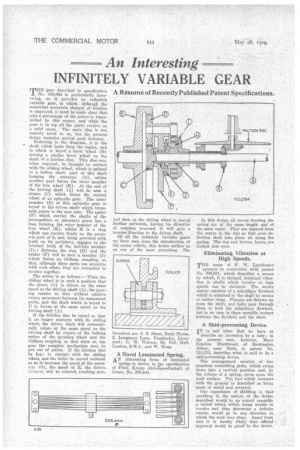
TEE gear described in specification No. 310,064 is particularly interesting, as it provides an infinitely variable gear, in which, although the somewhat uncertain element of friction is employed, it must be made clear that only a percentage of the power is transmitted by this means, and while the gear is in top all the parts revolve as a solid mass. The main idea is not entirely novel to us, but the present design contains . several good featnree. Referring to the • diagrani, A is the shaft which leads from the engine, and to which is keyed 'a bevel wheel (B) driving a similar bevel wheel on the shaft of a friction disc. This disc can, when required, be brought in' contact with the sliding wheel, which is splined to a hollow shaft, part of this shaft forming the eccentric (G), whilst another part forms the inner member of the free wheel (K). At the end of the driving shaft (A) will be seen -a pinion (C) which forms the central wheel of an epicyclic gear. The outer member (E) of this epicyclic gear is keyed to the driven shaft which transmits power to the rear axle. The spider (F) which carries the shafts of the intermediate or planetary gears has a boss forming the outer member of the free wheel (K), whilst H is a ring which can revolve freely on the eccentric part of G, and, being provided with teeth on its periphery, engages in the internal teeth of the bell-like member (I).• Between the ring (II) and the spider (F) will be seen a member (J) which forms an Oldham coupling, so that, although these parts are eccentric with each other, they are compelled to revolve together.
The action is as follows :—When the sliding wheel is in such -a position that the sleeve (G) is driven at the same speed as the driving shaft (A), the geartag rotates en bloc without relative rotary movement between its component parts, and the shaft which is keyed to E is driven at the same speed as the driving shaft (A).
If the friction disc be raised so that it no longer contacts with its sliding wheel, the driven shaft will automatically rotate at the same speed as the driving shaft by reason,of the locking action of the gyrating wheel and the Oldham coupling, so that when on top gear the complete mechanism may be put out of action. If the friction disc he kept in contact With the sliding wheel, and the latter be moved outward so as to increase the speed of the eccentric ((I), the speed of E, the driven element, will be reduced, reaching zero,
and then as the sliding wheel is moved further outwards, having its direction of rotation reversed, it will give a reverse'direction to the driven shaft.
Of • all the infinitely variable gears we have seen since the introduction of the motor vehicle, this device strikes us as one of the most . promising. The inventors are I. S. Shaw, Bank House, 2, Longmoor Lane, Fazakerley, LiverPool; O. W. 'Watson, 50, Pall Mall, London, S.W.1; and W. Heap.
A Novel Laminated Spring.
AN interesting form of laminated spring is sho'wn in the specification of Fried, Krupp Aktiagesellschaft, of Essen, No. 299,444.
In this design all leaves forming the spring are of the same length and of 'the same taper. They are tapered from the centre. to the tips .so that even deflection shall take place all along thespring. The top and bottom leaves are formed into eyes.
Eliminating Vibration at High Speeds.
THE name of F. W. Lanchester appears in connection with patent No. 309,931, which describes a means by which, it is claimed, torsional vibration in shafts which revolve at high speeds can be obviated. The device merely consists of a subsidiary flywheel which is attached to the skip by means of rubber rim. Flanges are thrown up from the shaft, and bolts pass through them to hold the subsidiary flywheel, brit in no ease is there metallic contact between the flywheel and the shaft
A Skid-preventing Device.
TT is not 'often that we have to
describe an invention by a lady; in the present case, however, Mary Emeline Blackwood, of Beckington. Abbey, near Bath, in patent :Co. 310,113, describes what is said to be a skid-preventing device.
The arrangement consists of two members resembling jacks, which swing down into a vertical position and, by the release of n spring, press upon the road surface. The foot which contacts with the ground is described as being made of metal and serrated.
Our experience of skidding is that anything in the nature of the device described would to an extent resemble a locked wheel, which, being unable to revolve and thus determine a definite course, would go in any direction -in. which the road may slope. Apart from this. it is hardly likely that •official • approval would be given to the device.


