


Patents Completed.
Page 26
If you've noticed an error in this article please click here to report it so we can fix it.
Another Shock-absorber—Composite Tires Roller Bearings for Big Ends.
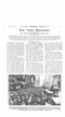
R. EsisaULT-FELTERIE, No. 28,517, dated 15th :\ [arch, 1913.—This shock absecber consists of a cylindrical easing having a groove, around its inner edge, of tapered crosssec.tien. Two shoes of similar cross-section lie in this groove,
being pivoted on fixed on a central shaft. This shaft has ri.5icily secured to it a lever, the motion of which is to be restrained.
A plate-spring is carried by the shaft, and this presses the two shoes outwasds into the tapered groove.
A roller at the bottom of the rasing is so situated that it bolds. the shoes up out of the groove, hut when the shaft is rotated one of the shoes is carried off the roller and the spring presses it down into the groove. During the return movement of the lover this shoe becomes tightly wedged in its groove and thus provides the necessary absorption of energy. A recess is provided at the outer edge of each of the shoe-s so that during the first turning movement, although one shoe is inoperative, when the other one is moved far enough to bring this recess opposite the wilier it call drop into its groove and provide a retarding effect to any further nestiou ; the other shoe, as before, retards the return motion.
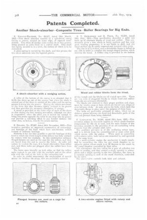
E. IlucaTie, No. 27,047, dated 24th November, 1913.—This invention psovides an improved constrnetion of connecting. rod bearings of the kind which have anti-friction rollers instead of ordinary bearings. Hitherto it has not been possible to provide bearings of this kind in which the whole length of the rollers was fully utilized by contact with the crankpin. In this construction ordinary flanged-brasses are used as the cage for the rollers, and they are bored from the end to receive the hitter. In order not LalCialy to weaken the cage, it is bored alternately from either cod, and these holes arc plugged after the rollers have been inserted.
The bores sipen laterally on both sides, so that the rollers make contact or. one side with the crankpin and on the other side with the wall of the hole in the connecting-rod.
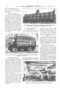
In order to render unnecessary the employment of special means for holding the plugs, they are preferably screwed. S. T. PaerrannsoN and It. PincE, No. 16,234, dated 15th July, 1915.—This specificatien describes a solid Lire built up of alternate blocks of wood and rubber. This construction gives a tire which is fairly resilient and has very good wearing properties; it is net liable to. skid, cud the tread surface can be easily removed and renewed when worn. The rim is of L-section, and a detachable flange is bolted to one side in order to complete the trough-shaped portion which. receives the tread. A rubber ring is provided in the bottom.
of the. (rough and the blocks are all seated upon this. There are iwo rows of staggered blocks in which wood and rubber segmsnts are arranged alternately. The blocks are retained in their proper position and alignment by wooden pegs or keys which are forced into elliptical slots between them. At some places the bolts which bold the detachable flange in place serve the purpose of these keys. The bolts are preferably arranged in tubes, which act as distance pieces between the fixed and detachable parts of the rim and prevent them being distorted.
1. Issmreoccar, No. 14,248, dated 19111 June„ 1913.—This invention relates to two-cycle engines in which crank-cliamber compressiou fer the air is used, and the main feature of the invention consists in the provision of an air-controlling valve separate from the eyliuder inlet valve. The auxiliary air-valve is of the oscillating rotary type, and it is driven from the connecting-rod or some other part
which moves with the piston. When used in connection with a sleeve valve, buth valves are connected to, and operated. by, the same lever. In a melti-cyllnder engine the mechanism is much simplified by connecting the valve for any crank chamber to an adjacent piston whose crank is at 45 degrees to the crank in the pump-chamber controlled by that valve. For convenience the two valves for a pair of cylinders are made to overlap, and they control .a single opening to atmosphere and a single opening to the two cylinders, but there is a separate opening to eat+ of the crank chambers, controlled by its valve. The sleeve-valve controls both inlet and exhaust.