


A Résumé of Recently Published Patent Specifications
Page 58
If you've noticed an error in this article please click here to report it so we can fix it.
Keeping Ott Engine Injectors Cool
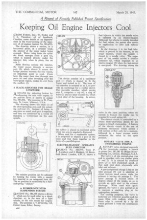
FROM Fodens, Ltd.' W. Foden and E. Twemlow, all of Sandbach, Cheshire, come details of an improvement in the water-cooling of the injectors of oil engines (patent No. 583,652).
The drawing shows a section, in a horizontal plane, of a cylinder head, the interior of the water jacket being exposed. Water rising from the cylinder block emerges from a port (I), which is located directly under the injector; this, when in place, lies on axis 2.
After flowing around the injector, the water passes through a narrow port (3), which directs it across the bridge portion between the two valves, an important point to cool. From here, the water then rises through two ports (4) and after sweeping over the valve-guide region, makes its exit from the outflow (5).
A SLACK-ADJUSTER FOR BRAKE LINKWORK
A MEANS for adjusting brakes by advancing the cam with respect to the pull-on lever, is shown in patent No. 583,052. The patentee is W. Freeman, St. Louis, Missouri, U.S.A.
The drawing shows the shaft (1) of the shoe-spreading cam and the actuating pull-rod (2). Instead of being in one piece as usual, each part is separate, and they are connected by a worm (3) engaging a wonnwheel on the cam spindle.
The relative position can be adjus ed by turning the worm with a special key inserted in an octagonal bore (4). The set position is maintained by a balland-spring "clicker."
A RUBBER-MOUNTED SUSPENSION SYSTEM
PATENT No. 583,335 shows a device which can be used either as a shock absorber, or, in the case of a light vehicle, as the sole means for suspension. The patentee is T. D'Orville, 115, Ember Lane, Esher, Surrey, The device consists of a stationary part (1) which is shaped to fit the frame and bolted to it. Thebore of this member is serrated as at 2, to provide an anchorage for a rubber sleeve. The movable member, which carries arm 3, comprises a cap (4), a ring of bolts (5) and an inner washer (6), which is just clear of the housing. In action,
the rubber is placed in torsional stress when the arm is angularly displaced.
When used for a suspension system, it is proposed to employ a pair of the units and link them together in the form of a parallelogram.
ELECTRO-MAGNET OPERATES FUEL INJECTOR
PATENT No. 583,977, from P. Luckham and J. Medgett, 10, Bramfield Road, London, S.W.11, shows a
fuel injector in which the needle valve is operated by an electro-magnet. Although the scheme is mainly intended for fuel valves, the patent also covers its application to inlet and exhaust valves.
In the drawing, I is the fuel inlet, which is ported to the bottom, in the usual manner, where the nozzle is closed by a needle valve. The upper part of the needle carries a circular armature (2), which responds to an electro-magnet (3) when till last-named is energized. The drawing shows the valve in the open position; when the current is broken the needle can be reseated by a coil spring (4).
The electric circuit is controlled by a rotary make-and-break driven by the engine in timed relationship. A feature of the electric circuit is the use of economy resistances which permit a full current to flow only for a moment, followed by a lesser current which maintains the valve in the open position.
ROTARY VALVE FOR A TWO-STROKE ENGINE
A ROTARY valve, designed expressly for two-stroke engines, is shown in patent No. 583,283 by Briggs Manufacturing Co., Detroit, Michigan, U.S.A. The valve is of the conical-plug type and is provided with two similar ports (1 and 2). It is rotated by overhead gears (3) at half crankshaft speed, so that each port deals alternately with inlet and exhaust.
A pre-compressed charge is fed to the inlet passage (4) and is admitted at about bottom dead centre, while the exhaust is leaving via passage 5. The latter passage is located about 10 degrees ahead of the intake, so as to provide an early start to the exhaust discharge. When used with spark ignition, the valve is also ported so as to uncover a sparking plug at the appropriate moment.
For cooling purposes, the valve is hollowed out wherever possible and the space filled with sodium, whilst its lower edge is covered by a lip (6) which protects it from the combustion flame.