


PATENTS SUMMARIZED.
Page 22
If you've noticed an error in this article please click here to report it so we can fix it.
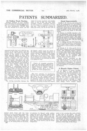
An Endless Track Machine.
Sergeant Hatfield, in four specifications, describes the arrangerneut and details of a tractor of the catertallar-type. The main specification, 113,102, deals with the machine as a whole, and the
principal novelty has to do with the suspension of the chassis proper upon the creeper frame. The Jatter has bearings located in the middleof its length. These bearings support A shaft. upon which is carried, through the medium of suitable brackets, the main chassis. This same -shaftalso carries the idle sprocket wheels, which:stake the drive from the differential shafts in the gearbox on the main chassis, and transmit it to the rear driving wheels on the creeper track. Clearly, with this arrangement, a considerable amount of angular Motion of themhassis ahoet the supporting shaft can take place without its' affecting to any marked extent the efficiency of the drive.'-'The fore part of the creeper track is carried upon a suitable guide wheel, the position of which, in a longitudinal direction, is adjust. able. Flanged nide pulleys, carried from thevereeper, frame bear upon the lower portion of the track, and carry the loan.
The &wing connection between the
creeper track frame and the main chassis is by four adjustable radius rods, and these are disposed diagonally. The .-nain chassis is disposed upon the supporting shaft in such a manner that its Qentre of gravity, is forward of that shaft. This tends to throw a little more weight on the front portion of the track,
B48 where it is most required, and &nether effect of this is that the only other necessary positive connection between the two frames is a tensional one at the rear end. This is made by a system of links and levers, one set on each side of the chassis, which couple the shafts of the driving wheels, which shafts are of course, carried in brackets on the creeper frame, to flat horizontal laminated springs fixed to the main frame. steering is effected by braking either chain track according to the direction in which it is desired to turn.
The same patentee, in specification 113,114, goes into detail of the design of the shoes for the creeper track. In : 113,115, the patentee describes a method of attaching rubber or other resilient spuds to the shoes of the creeper. Li 113,116 he describes in detail the method of carrying the flanged guide pulleys which run upon the upper side of that portion of the creeper which is in contact with the ground. These guide pulleys prevent lateral movement of the creeper. The above illustrations give a good idea of the machine and its detail components.
Detail Improvements.
112,998, C. H. Crawley and others, de7 scribe an arrangement for converting a Ford chassis for use as an a.gTimotor. An additional frame and axle are fitted, the Ford road wheels being removed and replaced by pinion wheels which gear into racks carried on the inside of the road wheel's. , E. Dobson, in 112,992, describes a device for preventing injury to the person as a result of an occasional backfire when starting up a petrol engine. The backfire has the effect of putting the starting handle jaws out of gear with the clutch on the engine-shaft.
W. C. Platts and the Cola Tyre Co., Ltd., in 113,129, describe a. construction of tyre tread which consists of alternating portions of steel-studded and rubber surface.
In 113,168, F. E. Ellis and fl. H. B. Ellis show a tipping gear for commercial lorries. The principal feature appears to be that, when loaded, the wagon can be tipped slowly, with greater mechani; cal advantage to the workman, and when empty can be operated more directly and at a higher speed.
Patent 113,120, published at the same time as the above, our readers will note with surprise, was taken out by Robert Bosch, of Stuttgart. It concerns a constructional ignition detail which we have not deemed it necessary to describe or illustrate.
A Ricardo Engine Patent,
H. R. Ricardo in patent specification No. 2725, of 1915, describes' an arrangement of internal-combustion engine from which he anticipates much better thermal efficiency than has hitherto been the 'rule. The charge enters in two parts, a more highly inflammable portion through a small pocket at the top of the Cylinders • the main charge, which consists almost
solely of air, entering -the main cy incler a little later in the stroke. The two portions are not intended to intermix. The small highly inflammable charge is exploded and passes into the main cylinder at high speed through a. narrow passage, thus raising the temperature and pressure of the body of the charge.