


MECHANICAL PRINCIPLES.
Page 16
Page 17
Page 18
If you've noticed an error in this article please click here to report it so we can fix it.
As Applied to the Loading and Unloading of Vehicles.
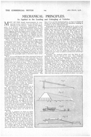
MANY OF THE detail improvements in commercial motor vehicles we owe directly or indirectly to the drivers. Taken in the aggregate, it is drivers' experience transmitted to the owner and, by him, to the manufacturer which draws attention to faulty details or incorrect design and often suggests ideas for improvement which, when the expert knowledge of the designer is applied to them, prove very valuable. Any driver is capable of complaining if things go wrong, but only a driver who has some knowledge of the machine under his control is capable of suggesting how to put it right. There are many drivers who have a thoroughly sound theoretical as well as practical knowledge of the mechanism of a motor vehicle, and who understand the underlying principles upon which it works. When a defect reveals itself and an improvement is required, we must first not merely locate the defect but ascertain how it is due to neglect to some essential principle. That is to say, we must get at the first cause of trouble and, starting from that point, we can set about constructing something the design of which recognizes the principle and is therefore more satisfactory. Now, it is a well-known fact that enormous losses, of time and money continue to result from the use of inefficient methods of loading and unloading. Similar inefficiency in a. carburetter leading to waste of fuel would cause an outcry at once. In fact, an enormous improvements in of energy has been directed to in fuel economy, resulting in a decrease in,thekcost of operation of the vehicles, or at least in limiting Dthe increase in the cost which would otherwise have occurred in consequence of the rise in price of the petrol. Meanwhile, antiquated methods of loading and unloading, resulting in even bigger losses in efficiency, have been allowed to be perpetuated. The writer suggests that this is largely duo to the fact that those concerned have taken the old,methods for granted, and have only tried to introduce improvements in details, without going back to first principles and trying to consider how those principles could be better applied to this important problem. All mechanism really depends on a few and extremely simple principles. The first of these—and one which has a most direct bearing in our case—is the. principle of the inclined plane.. We know that it takes a certain amount of work to raise a certain weight through a certain distance. The work may be measured by the product of the weight into the distance. It takes as much work to raise 1 lb. through 10 ft.. as to raise 10 lb. through 1 ft. When we come to censider the power required, the element of time-is introduced. Evidently it wants ten times as much power to do a certain piece of work in one minute as to do the same piece of work in 10 minutes. In Fig. 1, suppose we have to raise the weight (W) from the level of the line (AB) up to the level of the point (C). We might do the work by lifting the , weight directly upwards from A to C or by pushing it up the inclined plane (BC). By the time we get to the point (C) the work done would be the same in each case, if we neglect the possibility of wasting power in friction between the weight (W) and the surface of the plans up Which it is pushed. It follows that, if we use the inclined plane, we have a means of doing our work more slowly and therefore making it possible to do it with less power. Supposing the weight were placed at A, and a. rope attached to it led up to Cand there passed over a pulley, and suppose that a man then. pulled upon the rope in the direction shown by the arrow, if the power that the man could exert were sufficient he would succeed in raising the weight. If, however, he could not exert enough power and got, say, four other men to help him, the result might be to raise the weight from. A to C in one minute. Now supposing these four men were not available but there existed an inclined plane from B to C, the length of BC being five times the length of CA. Disregarding friction,. if the weight were placed upon the plane and a. rope attached passing over the pulley, the one man without help would he able to pull the rope at the same pace as the five men in the previous instance. He would have to travel .five times as far before he got the weight up to C, but by using the inclined plane he would have got what is called a mechanical advantage of five to one. Probably the inclined plane was the first of all mechanical devices known to man. One imagines that it wti,..a the only mechanism available to the builders of the Pyramids. Probably these were constructed by 'forming sloping roads or inclined planes as indicated in Fig. 2. The ,big blocks of stone were probably hauled over rollers by large numbers of men. When the first layer was in place an inclined road was built from A to B. The incline may have been a very slight one. Up this road the blocks re: quired for the second layer were hauled one by one. The road was then built up to the level CD and so On, and wlara the Pyramid had finally been constructed in. this way the sloping .road or inclined plane was again carted away piecemeal. It is possible that Stonehen e was constructed in a somewhat similar way. ow, the most obvious application of the principle of the inclined plane to the loading of vehicles is that indicated in Fig. 3. This shows an inclined plane extended from the open back of a lolly down to the ground. Up this plane heavy loads can be pushed or rolled, which could not be lifted direct o,n to the lorry by the men available. The inclined plane in this ease may take the form of runners and may be used both for loading and for unloading. The method is commonly adopted in dealing with barrels. These can . be turned on to their sides and rolled up the slope on to the lorry, where they are again tilted on to their ends. Similarly in unloading they can be turned on to their sides again, and controlled as they pass from the lorry to the ground.
At this point it will be well to explain that the following notes and the sketches accompanying them do not profess to provide complete practical solutions of loading difficulties. All that they are intended to i do is to suggest a few of the ways n which the principle of the inclined plane might be employed. The users or the loaders of vehicles may thus be encouraged to consider the principle in the light of their own special circumstances which must vary in every case.
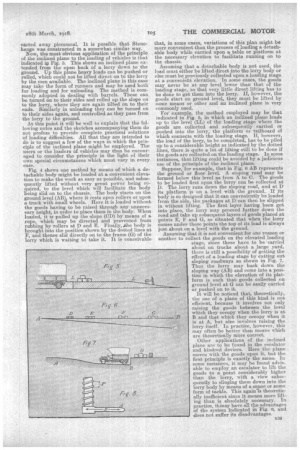
Fig. 4 shows one method by means of which a detachable body might be loaded at a convenient elevation to make the work as easy as possible, and subsequently lifted without very great power being required, to the level which will facilitate the body being slid on to the chassis. The body starts on the ground level (AB), where it rests upon rollers or upon a truck with small wheels. Here it is loaded without the goods having to be raised through any unnecessary height, in order to place them in the body. When leaded, it is pulled up the slope (CD) by means of a rope which may be directed and prevented from rubbing by rollers at D and E. Finally, he body is brought into the position shown by the dotted lines at F, and thence slid directly on to the frame (G) of the lorry which is waiting to take it. It is conceivable
that, in some cases, variations of this plan might be more convenient than the process of loading a detachable body while carried upon a table or platform at the necessary elevation to facilitate running on to the Chassis.
Assuming that a detachable body is not used, the load must either be lifted direct into the lorry body or else must be previously collected upon a loading stage at a convemeht elevation. In some cases, the goods may never be at any level lower than that of the loading stage, so that very little direct lifting has to be done to get them into the lorry. If, however, the goods start on ground level, they must be lifted by some means or other and an inclined plane is very commonly used.
For example, the method employed may be that indicated in Fig. 5, in which an inclined plane leads up to the level (LL) of the loading stage where the goods are collected and subsequently carried or pushed into the lorry, the platform or tailboard of which connects with the loading stage. If, however,
the load of the lorry, to be completed, has to be piled up to a considerable height as indicated by the dotted lines, there is quite a lot of lifting still to be done if the goods are collected on the loading stage. In some instances, that lifting could be avoided by a judicious use of the principle of the inclined plane.
Suppose, for example, that in Fig. 6 AB represents the ground or floor level. A sloping road may be
formed below this level as. from A to C. The goods to be loaded first upon the lorry can be collected at D. The lorry runs down the sloping road, and at 1) i
its platform s on a. level with the ground. If its body is so designed that it can conveniently be loaded from the side, the packages at D can then be slipped in without lifting. The first layer having been got into place, the lorry may proceed further down the road and take up subsequent layers of goods placed at points E, F and G, so situated that when the lorry comes under these points the top of its load is always just about on a level with the ground.
Assuming that it is not convenient for one reason or
another to collect the goods on the elevated loading stage, since these have to be carried about on trucks about a large yard, there is still a possibility of getting the effect of a loading stage by cutting out sloping roadways as shown in Fig. 7. Thus the lorry may back down the sloping way (AB) and come into a position in which the elevation of its platform is such that goods collected on ground level at G can be easily carried or pushed on to it.
It will be noticed that, theoretically,
the use of a plane of this kind is not efficient, because it involves not only raising the goods between the level which they occupy when the lorry is at B and that which they occupy when it is at A, but also involves raising the lorry itself. In p.ca,ctice, however, this may often be better than means which are theoretically mbre correct.
Other applications of the inclined
plane are to be found in the escalator and kindred devices. Here the plane moves with the goods upon it, but the first principle is exactly the same. In sonic instances, it may be found advisable to employ an escalator to lift the goods to a point considerably higher than the lorry, with a view subsequently to slinging them down into the lorry body by means of a crane or some form Of tackle. This again7s theoretically inefficient since it means more lifting than is absolutely necessary. In practice, itainay.. have all the advantages of the system indicated in Fig. 6, and does not suffer its disadvantages. The partieular point, of course, is that it allows the whole of the load to be put into position without any lifting being necessarily done by manual power. Reverting to Fig. 6, it will be seen that, here, again, we are theoretically wrong, since we deliberately carry the lorry and some of its load to a lower level and subsequently have to raise the fully-loaded lorry from the lowest level of all to the level of the ground. In practice, however, this is a. minor consideration as compared with the avoidance of lifting by hand.
Finally, before turning to a consideration of other mechanical principles, it is necessary to point out briefly that the ordinary screw is, as a matter of fact, in the nature of an inclined plane. Fig. 8 shows part of a, screw with a square thread. In essence this is much the same as a spiral staircase, only in the case of the screw it is usually the spiral which rotates,
whereas in the ease of the staircase the load to be lifted must circulate round the spiral. While the • screw makes one revolution the load lifted by it is raised the distance (P), called the pitch of the screw. Meanwhile, the force used to turn the screw and applied, let us say, at the point A, has travelled through a distance equal to the circumference of a circle having a radius (R). Suppose the screw has one thread to the inch and there are 10 inches, then the movement of the point A is 10 X r, equals about 31.4 in. The load meanwhile is raised 1 in., so that the machanical advantage is in this case 31.4 to one and the screw corresponds to an inclined plane with a very gentle inclination. The actual application of the screw to loading and unloading cannot, however, be advantageously considered until we have dealt with the mechanical principle of the lever.