 1
1 2
2 3
3 4
4 5
5 6
6 7
7 8
8 9
9 10
10 11
11 12
12 13
13 14
14 15
15 16
16 17
17 18
18 19
19 20
20 21
21 22
22 23
23 24
24 25
25 26
26 27
27 28
28 29
29 30
30 31
31 32
32 33
33 34
34 35
35 36
36 37
37 38
38 39
39 40
40 41
41 42
42 43
43 44
44 45
45 46
46 47
47 48
48 49
49 50
50 51
51 52
52 53
53 54
54 55
55 56
56 57
57 58
58 59
59 60
60 61
61 62
62 63
63 64
64 65
65 66
66 67
67 68
68 69
69 70
70 71
71 72
72 73
73 74
74 75
75 76
76 77
77 78
78 79
79 80
80 81
81 82
82 83
83 84
84 85
85 86
86 87
87 88
88 89
89 90
90 91
91 92
92 93
93 94
94 95
95 96
96 97
97 98
98 99
99 100
100 101
101 102
102 103
103 104
104 105
105 106
106 107
107 108
108 109
109 110
110 111
111 112
112 113
113 114
114 115
115 116
116 117
117 118
118 119
119 120
120 121
121 122
122 123
123 124
124 125
125 126
126 127
127 128
128 129
129 130
130 131
131 132
132 133
133 134
134 135
135 136
136 A Transmission Layout
Page 92
If you've noticed an error in this article please click here to report it so we can fix it.
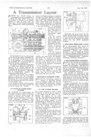
PATENT No. 773,595 shows an arrangement for the transmission of a vehicle, the chief feature being that the flywheel is located in an unusual position in order to make room for other units. (Harry Ferguson Research Ltd.," Abbotswood," Stow-on-the-Wold. Glos.)
The flywheel (I) is not carried directly on the end of the engine crankshaft (2), but is journalled on the front bearing (3) of the gearbox. It is connected to the crankshaft by a torsionally rigid but otherwise flexible coupling (4).
The clutch is pressed into engagement by a single large spring (5) and can be released by a central push-rod (6) extending right through the primary and mainshafts of the gearbox. The pushrod is hydraulically actuated, the mechanism being shown at 7.
Separating the engine and flywheel creates a space for the inter-wheel differential (8) of the front axle. Another differential (9) in the gearbox divides the drive between the front axle and the rear drive-shaft (10).
Few details are given of the gearbox itself, because it has been covered by an earlier patent, No. 731,938.
AN UNUSUAL COMBUSTION SYSTEM
ASCHEME for approaching oil engine economy without needing an expensive injection pump forms the subject of patent No. 773,583. (F. Stumpfig and C. Bellwinkel, 8 Thornerstrasse, Niirnberg, Germany.) The engine described compresses a very rich mixture, so rich that it will not self
Ignite at the high compression employed. A little air is then applied, to bring it into the ignitable range, and a sparking plug used. The flaming mixture, still rich, is then blown into the main air space where combustion is completed.
The drawing shows the inlet valve (1) in the open position. A combustion chamber (2) contains the exhaust valve (3). Also controlled by the inlet valve is a rich-mixture supply tube (4).
On the suction stroke, air only is drawn in through the inlet (5) and fills the main cylinder space. Meanwhile, the combustion chamber receives a fuel-rich charge, the two charges remaining separate.
On the compression stroke, much of the air remains in the cylinder, but some enters the chamber and dilutes the mixture to a combustible degree. A taneential inlet causes the fuel to be subjected to an intense whirling motion which holds it to the hot walls of the chamber. evaporating or even cracking it.
At top dead centre, the fired mixture is blown through passage 6 into the
compressed-air region (7). It must travel in this direction because the piston boss (8) is at that moment obstructing the lower exit (9).
REPAIRING TUBELESS TYRES
PATENT No. 772,709 gives details of a method of repairing tubeless tyres by injecting rubber into the cut and subsequently vulcanizing. (United States Rubber Company, Rockefeller Center, New York, U.S.A.)
AN AIR INTAKE HEATER
IT is often necessary to burn a small I quantity of fuel in the air intake of an oil engine with the object of preheating the ingoing air to assist -starting. This scheme has the disadvantage that the heat is obtained at the expense of ingoing oxygen, so that combustibility is lessened just when it should be highest. An improved method of burning the heater fuel is shown in patent No. 744,301. (Ruston and Hornsby Ltd., Sheaf Iron Works, Waterside South, Lincoln.)
It is proposed to leave the main air. intake undisturbed and to attach a small additional intake for the burner. In the drawing, 1 is the main intake and 2 the burner attached thereto.
The burner consists of a small jet (3) directed towards a venturi in which is placed an electric hot-wire igniter (4). A butterfly valve (5) is used to isolate the unit when out of use. Preferably, the starter-motor (6), the igniter and the valve-operating solenoid (7) are all wired into a common circuit so that the act of pressing the starter switch sets the • whole equipment working.
A ROTATING SHROUDED VALVE I T is advantageous that valves be permitted to rotate slowly, but if a valve is shrouded this is not normally permissible. Patent No. 773,651 discloses a valve in which the shroud is a separate member which remains in the same position yet allows the valve to turn. (Maschinenfabrik AugsburgNurnberg, NUrnberg, Germany.) A PRE-COMBUSTION CHAMBER
PATENT No. 773,278 gives details of a new form of pre-combustion chamber for oil engines. The aim is to obtain a more thorough intermixture of•
the air and fuel. (Maschinenfabrik Augsburg-NUrnberg A.G. Stadbachstrasse 7, Augsburg, Germany.) The chamber is machined in the cylinder head to the outline shown. The injector (1) is located at the top and an insert plug (2) at the bottom, the latter being held by a screwed ring (3). The bottom of the injector is radially slotted as shown at 4.
During compression, the air passes through tangential bores (5) and spins rapidly upwards through the conical annulus (6), continuing up the walls of the chamber. Upon reaching the top, the air is reversed by the roof curvature and descends with the fuel, some of it mixing in the radial slots which are provided in the injector.