


WORKSHOP WAYS LEYLAND DAF ROADRUNNER
Page 61
Page 62
Page 63
Page 64
If you've noticed an error in this article please click here to report it so we can fix it.
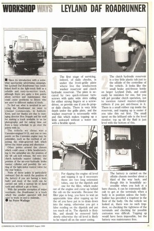
The first stage of servicing, indeed, of daily checks, is under the front-grille plate where live the windscreen washer reservoir and clutch hydraulic reservoir. The plate is secured by two quick-release turnscrews with quite wide slots calling for either strong fingers or a screwdriver, so provide one if you do proper daily checks. There is very little depth under the grille plate, and the washer reservoir is necessarily wide and thin which makes topping up a little awkward without a water can with a flexible spout.
For dipping the engine oil level and topping it up if necessary there are two long extension tubes, one for the dipstick and one for the filler, which snake Out of the engine and come up behind the cab on the nearside. Because the filler pipe is long, you have to wait an appreciable time after topping up for the oil you have put in to drain down into the sump, otherwise you get a false reading on the dipstick and put too much oil in. The dipstick is flexible, and should be removed fairly slowly otherwise the .oil level is likely to be wiped off on the outer casing. The clutch hydraulic reservoir is a tiny little plastic tub just to the offside of the centreline of the vehicle. It looks like the small brake anti-freeze bottle on larger Leyland Dafs, and could easily be mistaken for one, but you will get peculiar clutch operation, not to mention ruined master-cylinder rubbers if you put anti-freeze in it. There is a small rubber cup inside the reservoir, and topping up is easier if you take this out first. The small spout on the lefthand side is the level monitor; top up till the fluid is just level with the bottom of this.
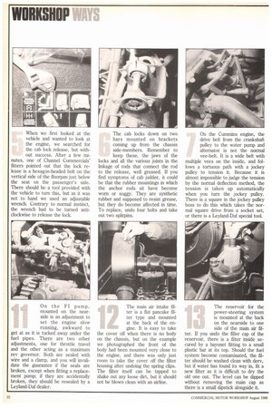
The battery is carried on the offside chassis member about a third of the way back, and though this is beautifully accessible when you look at a bare chassis, it can be extremely difficult to get at the terminals when a body is in position unless the bodybuilder has provided a trapdoor in the floor of the body. On the vehicle we looked at, there was no such trapdoor, so checking the tightness of the terminals and checking for possible corrosion was difficult. Topping up would have been impossible, but the battery was maintenance free. When we first looked at the vehicle and wanted to look at the engine, we searched for the cab lock release, but without success. After a few mi nutes, one of Channel Commercials' fitters pointed out that the lock release is a hexagon-headed bolt on the vertical side of the floorpan just below the seat on the passenger's side. There should be a tool provided with the vehicle to turn this, but as it was not to hand we used an adjustable wrench. Contrary to normal instinct, the wrench had to be turned anticlockwise to release the lock. The cab locks down on two On the Cummins engine, the bars mounted on brackets drive belt from the crankshaft coming up from the chassis pulley to the water pump and side-members. Remember to alternator is not the normal keep these, the jaws of the vee-belt. It is a wide belt with locks and all the various joints in the multiple vees on the inside, and fol linkage of rods that connect the rod lows a tortuous path with a jockey to the release, well greased. If you pulley to tension it. Because it is find symptoms of cab judder, it could almost impossible to judge the tension be that the rubber mountings in which by the normal deflection method, the the anchor rods sit have become tension is taken up automatically worn or soggy. They are synthetic when you turn the jockey pulley.
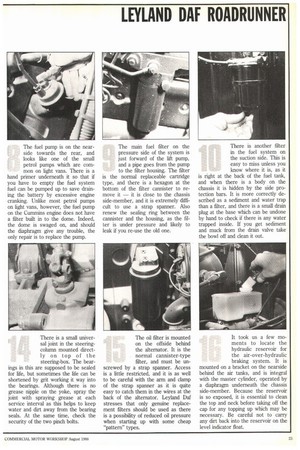
rubber and supposed to resist grease, There is a square in the jockey pulley but they do become affected in time. boss to do this which takes the nor To replace, undo four bolts and take mal square drive from a socket set, out two splitpins. or there is a Leyland-Daf special tool. The fuel pump is on the nearside towards the rear, and looks like one of the small petrol pumps which are common on light vans. There is a hand primer underneath it so that if you have to empty the fuel system fuel can be pumped up to save draining the battery by excessive engine cranking. Unlike most petrol pumps on light vans, however, the fuel pump on the Cummins engine does not have a filter built in to the dome. Indeed, the dome is swaged on, and should the diaphragm give any trouble, the only repair is to replace the pump. The main fuel filter on the pressure side of the system is just forward of the lift pump, and a pipe goes from the pump to the filter housing. The filter is the normal replaceable cartridge type, and there is a hexagon at the bottom of the filter carmister to remove it — it is close to the chassis side-member, and it is extremely difficult to use a strap spanner. Also renew the sealing ring between the caimister and the housing, as the filter is under pressure and likely to leak if you re-use the old one. There is another filter in the fuel system on the suction side. This is easy to miss unless you know where it is, as it is right at the back of the fuel tank, and when there is a body on the chassis it is hidden by the side protection bars. It is more correctly described as a sediment and water trap than a filter, and there is a small drain plug at the base which can be undone by hand to check if there is any water trapped inside. If you get sediment and muck from the drain valve take the bowl off and clean it out.
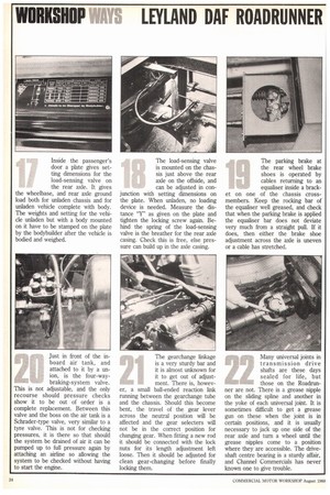
On the Fl pump, mounted on the nearside is an adjustment to set the engine slow running, awkward to get at as it is tucked away under the fuel pipes. There are two other adjustments, one for throttle travel and the other acting as a maximum rev governor. Both are sealed with wire and a clamp, and you will invalidate the guarantee if the seals are broken, except when fitting a replacement pump; if they are accidentally broken, they should be resealed by a Leyland-Daf dealer. The main air intake filter is a flat pancake filter type and mounted at the back of the engine. It is easy to take the cover off when there is no body on the chassis, but on the example we photographed the front of the body had been mounted very close to the engine, and there was only just room to take the cover off the filter housing after undoing the spring clips. The filter itself can be tapped to shake out any loose dirt, but it should not be blown clean with an airline. The reservoir for the power-steering system is mounted at the back on the nearside to one side of the main air filter. If you undo the filler cap of the reservoir, there is a filter inside secured by a bayonet fitting to a small plastic bar at its top. Should the fuel system become contaminated, the filter should be washed clean with derv, but if water has found its way in, fit a new filter as it is difficult to dry the old one out. The level can be dipped without removing the main cap as there is a small dipstick alongside it. There is a small universal joint in the steeringcolumn mounted directly on top of the steering-box. The bear ings in this are supposed to be sealed for life, but sometimes the life can be shortened by grit working it way into the bearings. Although there is no grease nipple on the yoke, spray the joint with spraying grease at each service interval as this helps to keep water and dirt away from the bearing seals. At the same time, check the security of the two pinch bolts. The oil filter is mounted on the offside behind the alternator. It is the normal cannister-type filter, and must be un screwed by a strap spanner. Access is a little restricted, and it is as well to be careful with the arm and clamp of the strap spanner as it is quite easy to catch them in the wires at the back of the alternator. Leyland Daf stresses that only genuine replacement filters should be used as there is a possibility of reduced oil pressure when starting up with some cheap "pattern" types. It took us a few moments to locate the hydraulic reservoir for the air-over-hydraulic braking system. It is mounted on a bracket on the nearside behind the air tanks, and is integral with the master cylinder, operated by a diaphragm underneath the chassis side-member. Because the reservoir is so exposed, it is essential to clean the top and neck before taking off the cap for any topping up which may be necessary. Be careful not to carry any dirt back into the reservoir on the level indicator float. Inside the passenger's door a plate gives setting dimensions for the load-sensing valve on the rear axle. It gives the wheelbase, and rear axle ground load both for unladen chassis and for unladen vehicle complete with body. The weights and setting for the vehicle unladen but with a body mounted on it have to be stamped on the plate by the bodybuilder after the vehicle is bodied and weighed. The load-sensing valve is mounted on the chassis just above the rear axle on the offside, and can be adjusted in con junction with setting dimensions on the plate. When unladen, no loading device is needed. Measure the distance "Y" as given on the plate and tighten the locking screw again. Behind the spring of the load-sensing valve is the breather for the rear axle casing. Check this is free, else pressure can build up in the axle casing. The parking brake at the rear wheel brake shoes is operated by cables returning to an equaliser inside a brack et on one of the chassis crossmembers. Keep the rocking bar of the equaliser well greased, and check that when the parking brake is applied the equaliser bar does not deviate very much from a straight pull. If it does, then either the brake shoe adjustment across the axle is uneven or a cable has stretched.
Just in front of the inboard air tank, and attached to it by a union, is the four-waybraking-system valve. This is not adjustable, and the only recourse should pressure checks show it to be out of order is a complete replacement. Between this valve and the boss on the air tank is a Schrader-type valve, very similar to a tyre valve. This is not for checking pressures, it is there so that should the system be drained of air it can be pumped up to full pressure again by attaching an airline so allowing the system to be checked without having to start the engine. The gearchange linkage is a very sturdy bar and it is almost unknown for it to get out of adjust w.6044.4 ment. There is, howevCr, a small ball-ended reaction link running between the gearchange tube and the chassis. Should this become bent, the travel of the gear lever across the neutral position will be affected and the gear selecters will not be in the correct position for changing gear. When fitting a new rod it should be connected with the lock nuts for its length adjustment left loose. Then it should be adjusted for clean gear-changing before finally locking them. Many universal joints in transmission drive shafts are these days sealed for life, but those on the Roadrunner are not. There is a grease nipple on the sliding spline and another in the yoke of each universal joint. It is sometimes difficult to get a grease gun on these when the joint is in certain positions, and it is usually necessary to jack up one side of the rear axle and turn a wheel until the grease nipples come to a position where they are accessible. The driveshaft centre bearing is a sturdy affair, and Channel Commercials has never known one to give trouble.