


Infinitely Variable Gear in British Chassis
Page 46
If you've noticed an error in this article please click here to report it so we can fix it.
ABRITISH commercial-vehicle manufacturer is taking up the construction of the Beier infinitely variable gear and a chassis incorporating it will, " The Commercial Motor" understands, be shown at Earls Court in September. The gear, which was invented by Dr. Josef Beier, at one time chief engineer of the Brown Boveri concern at Mannheim, works on the friction-cone principle, but in this instance the power is transmitted by oil drag between the driving and driven members.
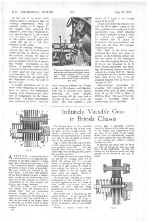
Reference to Figs. 1 and 2 will show that tapered. discs (B) mounted on a splined shaft (A) are interleaved between flanged discs (D). It is important to note that the flanged discs make contact with the tapered discs at only the side faces of the flanges. There is, however, an oil film present in these areas, so that there is no metal-to-metal contact.
A36
The flanged discs are also mounted on a stilined shaft (E) and in both cases the discs are free to slide axially. To obtain a variation of the speed ratio between the respective shafts it is necessary only to vary the depth of penetration of the tapered discs.
Fig. 1, which shows the tapered discs at full penetration, represents the lowgear position, whilst Fig. 2, with the tapered discs making contact at their outer edges with the flanged discs, shows the top-gear position.
To change the ratio, the tapered discs are moved by swinging arms (F) in which the splined shaft E is carried. Power is transmitted through the drive pinion Q to idler pinions P, which in turn convey the drive to a common central wheel, so that the output and input shafts are coaxial. Spring C exerts end thrust on the discs.
The foregoing is intended as a simple explanation of the principle, as in a practical application there is a series of both tapered and flanged discs, the number of discs employed being governed by the torque that it is desired to transmit.
The whole unit is mounted on the engine flywheel. A gear suitable for fitting to an engine of 140 b.h.p. is carried in a flywheel housing measuring 22 ins, in diameter, with an axial length of 9 ins.
Neither a separate clutch nor a
reverse gear is necessary. Another important feature is that when the speed of the output shaft approaches 15.-20 per cent. of the speed of the engine, direct drive is automatically engaged, the whole mechanism then revolving as a unit without any relative rotation between the discs.
in practice, this means that for 80-90 per cent. of driving no wear can take. place in the mechanism. As the unit runs in oil, the degree of wear over long periods of use should, in any case, be