


Oil Pump with Automatic Pressure Limit.
Page 36
If you've noticed an error in this article please click here to report it so we can fix it.
TOprevent the generation of excessive pressule due to cold and viscous oil is the object of a modified design of lubricating-oil pump shown in patent No, 557,366, by Mortis Motors, Ltd., T. Brown and W. Thornas, all of Engines Branch, Courthouse Green, Coventry The essence of the scheme is the use of a spring-loaded clutch in the drive, which slips after a certain torque value is exceeded.
The clutch is built into the driving spindle and is totally enclosed by a casing (1) with a screwed-on lid. The casing is positively driven and turns the lower spindle through the medium of a friction plate (3). A durable bush (2) permits the clutch to slip without causing undue wear.
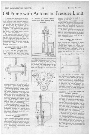
AN IMPROVED OIL SEAL FOR WHEEL HUBS
PATENT No. 557,122 comes from J. Brockhouse and .Co., Ltd., and A. Dear, both Of Hill Top, West Bromwich, and discloses a sealing device for
retaining lubricant in bearings such as wheel hubs. The scheme is intended primarily for bronze-bushed bearings.
The drawing shows a typical bushed hub, one end of which is closed by a cap, whilst the other carries the housing (1) of the oil seal. The latter consists of two L-section rings enclosing a felt washer (3) of the usual type. The novelty lies in the provision of a clear space (2) around the outside of the rings which is filled with a plastic material that will accommodate itself to slight errors in concentricity. The material suggested for filling the space is grease of high melting point; it is not primarily intended to act as a lubricant but only as a flexible fixing for the sealing ring. The grease is introduced through a nipple (4) which leads only to space 2.
A COMPACT OPPOSED-PISTON ENGINE
THEopposed-piston engine has many advantages, but hitherto its excessive overall height has probably militated against its more general adoption. Patent No. 557,074, from Sulzer Freres .S.A., Winterthur, Switzerland, .shows an improved design.
The drawing indicates the general layout, which incorporates two banks of cylinders (4 and 7), each of which ' houses an opposed pair of pistons. In this instance, the angle of slope is such that a ,single crankshaft (5), at the lower end, can act for both banks, but separate c,7ankshafts (3 and 8) are required at the top.
The main power shaft (6) is centrally located and is coupled to the crankshafts by a single large gearwheel (9). The circle (1) indicates a charging blower which is driven by a gear train shown generally at 2.
The layout permits the use of the space between the cylinder banks to be used for the accommodation of air and exhaust piping, fuel and oil pumps and their associated pipes, thus giving a clean, compact profile.
' SHACKLE-BOLT EXTRACTING TOOL 'TO facilitate the extraction of seized shackle bolts is the object of a garage tool shown in patent No. 557,276, by J. Brassington Montrose, Eghvyswen Road, Denbigh. Use is made of the grease-nipple hole a's a means for applying the withdrawing force. • In the drawing, 5 is a long sleeve, internally threaded to receiye a long bolt member (4) having a tommy-holed head (2), Into the end of the bolt member is inserted a small plug (3). which fits the thread in the hole vacated by the removal of the grease nipple. In operation, the plug is inserted, the head (2) held by a tommy-bar, and the sleeve rotated by its handle (1); the shackle bolt is thus withdrawn from its spring into the sleeve (5).
HOUSING A SPARKING PLUG IN AN OIL ENGINE
THE conversion of an oil engine to run on producer gas presents many problems, not the least of which is to find space for a sparking plug in a head not designed to receive it. To use the injector bore is the obvious solution but, in overhead-valve engines, the oil mist may adversely affect the plugs and their leads. An. improved scheme is shown in patent No 556,790, by W. Morison and the' .Eastern National Omnibus Co., Ltd., Chelmsford.
In the drawing, a standard plug (5) is screwed into an adaptor which fits the injector port (4).. The adaptor carries a tubular extension (7) lined with a glass tube (2) to act as an insulator. This passes completely through the valve cover (3) and is surmounted by a cap-nut (1) which forms the terminal. The adaptor may be clamped in • place by a flange (6) which receives the injector studs.