


WILL THIS TWO-STROKE 0
Page 26
Page 27

Page 28
Page 29
If you've noticed an error in this article please click here to report it so we can fix it.
I ENGINE SET A FASHION?
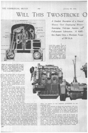
A Detailed Description. of a General Motors Unit Employing. Blower Scavenging, Unit-typeInjectors. arpr Full-pressure Lubrication. A 4.647litre Engine Gives a Maximum Torque of 350 lb./ft.
ET is only natural that, at the present time, there shouldbe considerable tought devoted to what the posttar period will give us in the way of ew or improved types of power unit, 3 . much experimental and practical ..ork is being accomplished about tich the general public is not, as yet, eimitted to learn.
We have for so. long become acct.'sslued to the four-stroke engine burning ither petrol or oil that the idea .of two-stroke usurping its position haS ever gone . far beyond the -stage of .sectflation. There are, of course, nod .reasons why the large-capacity etrol-driven two-stroke has not -been eveloped, but there has always been ae possibilityof the two-stroke oiler ecorning a serious :rival to the fourmake unit for use in road vehicles.
As may be known, such forms of prime-mover are extem vely employed in inarine..eircles and, to a, lesser 'extent,
ir stationary-plant duties. but -in this country, at least, sere is not a single example to be found in road-transport chides. So far, their use has been snore or less confined ).agrieultural'practice, but in the United States the ' two
;rOke oiler is employed extensively in coaches'and lorries: Although not a.product :of. the -exigencies of .war, the vo-stroke oil engine which has been developed by teneral iotors Corporation :.:,has.. marl. conSiderahle progress as A !SUlt of it at.d.is oow :proving itself. in 'almost every conivable: •forni-„.. of service from driv.ing : railcars ' t4 the
aore lowly duty'of forMing the prime-11161/er Of 'sniall power
snerators. Apart from the fact-that the details in its esign may, in -themselves, provide interesting comparison ith the existing petrol two-stroke engines and four-stroke
oilers, we believe it has immense possibilities in our particular field.
It may be of interest to those not conversant with twostroke oil engines to deal briefly with the various phases which go towards completing the cycle of operations in the G.M. engine, particularly as 'it -differs from the usual system of inspired induction as is normally employed in petrol two-stroke units. With the piston at the .lowest point of its travel, air pre-compressed under the influence of a blower .enters the . -lower part of the cylinder via holes radially disposed in it, the 'piston. in its downward traVel having uncOvered these ports. The exhaust valve'sbeing open, the ifirtishing serves to scavenge 'the cylinder, hut irrimediately the rising. piston closes the ports the extaust valves shut, the air thereafter being comptes.sed. to i-ith of its initial volume,
Just before the piston reaches top dead centre,the required quantity of atomized fuel is sprayed into the cylinder in the usual way. Ignition takes place and the resultant expansion forces the piston down. The exhaust valves open, and the air-admission ports are again tincovered by the piston, pre-compressed air again rushes in to scavenge the cylinder and the cycle of operations is repeated. It will be appreciated from the foregoing that, as no mixture enters the crankcase:, there is no difficulty in lubricating the heavily loaded bearings.
Such is the design of this engine that it can be built with any nnmber of eylinders from one to six, the hore and stroke of 4i ins. and 5 ins. respectively being common to ail units. The displacement per cylinder is 70.9 cubic ins., so that a four-cylindered power_ unit, such as might be installed fit a motor coach or heavy goods machine, would have a total displacement of 283.6 cubic ins: or 4.647 litres. Incidentally, 70.9 is near enough to 71 for the type designatiOn chosen of series 71.
As a four-cylindered engine, the rnaximuni output is given as 80 h,p. at the nominal speed of 1,200 r.p.m., the'COntinnolls output rating being 60 h.p. at the same speed. The b.m.e.p. at the latter output is 70 lb. per sq. in. and the maximum torque 350 lb./ft. at speeds between 800 r.p.m. and 1,200 r.p.m. High torque at low engine revolutions is a characteristic of two-stroke units, and it is this feature which permits an engine banging on to a load without distress.
By way of comparison, it may be of interesi to mention that a typical six-cylindered fourstroke oil engine of 7.88 litres capacity claims a maximum torque of 342 lb./ft. at 1,800 r.p.m
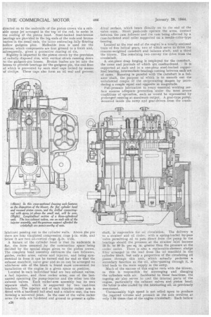
Dealing with the construction of the G.M. two-stroke oiler, the cylinder Kock and crankcase unit is box-like in appearance and iformed as a one-piece casting in alloy iron. The respective ends of the block are identical, so that the flywheel housing and gear train may be mounted at whichever cud is found more convenient Dry cylinder liners are . used, the holes drilled in them which, of course, coincide with those in the cylinder block being 64 in number and p-4in. diameter.
A point of interest hei-e is that the liners are an easy, -fit in the cylinder block, a feature which considerably simplifies -removal and replacement. A high carbon-stee: drop forging is used for the crankshaft, the main and big end journals of which are electrically hardened. In viev, of the heavy loads imposed, it is imperative that the crankshaft should be given ample support and this is pro. vided by arranging a lead-bronze lined bearing on each side of each throw, the bearing dimensions being 3i ins. diameter by 14 ins. long. The diameter of the crank-pins is 24 ins, and their length 1 25-32 ins.
In view of the disposition of the crank throws, necessitated by the fact that the engine operates on the two-stroke principle, special attention has been given to the question of balance and, so far as the crankshaft is concerned, a system of counterweights is used, the component being corrected both statically and dynamically. As the engine is lubricated under pressure, the crankshaft is suitably drilled to this end.
Drillings are taken up through the connecting rods from the big end to the small end, oil from the latter being directed on to the underside of the piston crown via a suitable spray jet arranged in the top of the rod, to assist in the cooling of the piston head. Steel-backed lead-bronze bearings are provided in the big ends of the rods and bronze bushes in the small ends, the latter embracing fully floating hollow gudgeon pins Malleable iron is used for the pistons, which components are first ground to a finish and, subsequently, given a protective coating of -tin.
Rigidity is imparted to the piston crown by the provision of radially disposed ribs, with vertical struts running down to the gudgeon-pin bosses. Bronze bushes are let into the bosses to provide bearings for the gudgeon pin, the end float of whic4 is prevented by sunk steel caps locked by means of circlips. These caps also form an 'oil seal and prevent lubricant passing out to the cylinder walls. Above he pin there are four tin-plated compression rings Fin. wide, and below it are two oil-control rings wide.
A feature of the cylinder head is that its underside is flat, the form assumed by the combustion space being decided by the special shape given to the piston crown. The complete head assembly embraces the cam followers, guides, rocker arms, valves and injector, and being symmetrical in form it can be turned end for end so that the exhaust manifold, valve gear and so on can be arranged on whichever side of the block is found more convenient for installation of the engine in a given space or position.
Located in each individual head are two exhaust valves, a fuel injector, and three rocker arms, one of the lastnamed operating the pump-injector and the other two the exhaust valves. Each rocker-arm assembly has its own separate shaft, which issupported by two cast-iron brackets. The injector end of each injector rocker arm is fitted with a hardened ball stud and a relative seat, the two forming a universal joint. In the case of the valve rocker arms the ends are 'hardened and ground to present a cylin
drical surface, which bears directly on to the end of the valve stein. Short push-rods operate the arms, contact between the cam follower and the cam being effected by a case-hardened steel roller supported on a needle-roller-type -bearing. Located at the rear end of the engine is a totally enclosed train of five helical gears, two of which serve to drive the counter-weighted camshaft and balance shaft, and a third the blower. The remaining two convey the drive from the crankshaft.
A onezpiece drop forging is employed for the camshaft, the cams and journals of which are. casehardened. It is supported at each end in -a one-piece steel-backed copperlead bearing, intermediate bearings coming between each set of cams. Running in parallel with the camshaft is a balance shaft, the purpose of which is to smooth out the unbalanced couple of the reciprocating masses by introducing a couple equal and opposite in magnitude.
Full-pressure lubrication to every essential working surface ensures adequate protection under the most severe conditions of operation, such as would be represented by prolonged running at maximum output. A gear-type pump, mounted inside the sump and gear-driven from the crank
shaft, is responsible for oil circulation. The delivery ,s to a strainer and oil cooler, with a spring-loaded by-pass valve permitting oil to pass direct from the 'pump to the bearings should the pressure at the strainer inlet become 25 lb. to 30 lb. per sq. in. greater than the pressure at the cooler outlet. There is also a replaceable-element sludge filter arranged in the lead from the oil manifold in the cylinder block, but only a proportion of the circulating oil passes through this unit, which actually performs a secondary function as the oil, after-passing through it, is bled back to the main supply in the sump.
Much of the success of this engine rests with the blower, as this is responsible . for scavenging and charging the cylinders with air. Incidental to thesefunctions, the ingoing air also serves to• cool the internal parts of the engine, particularly the exhaust valves and piston head; the latter is also cooled by the lubricating oil, as previously mentioned.
Unreasonably high speed is not relied upon to produce the required volume and pressure as the unit revolves at only 1.94 times that of the engine crankshaft Each hollow rotor carries three lobes and, in order to provide a more continuous and uniform airflow, the axes of the lobes are arranged out of parallel with the rotor. Incidentally, the airflow through the cylinder is uni-directional, because the air is always travelling from the air-belt in the cylinder wall towards the head.
The injectors used in the G.M. engine are known as the unit type, in that the pump. and injector mechanism proper _are built as one component. An injector can thus be fitted or removed from the engine after the manner of a sparking plug, although the process naturally
takes a little longer. Some of the outstanding advantages of the type are that abnormal, high. injectionpressures may be employed even up to 20,000 lb. per sq. in., there is never any
need to bleed the system as is necessary where external piping is used, and wave effects are minimized,
Another point, 'too, is that the injector is cooled by the circulation of the fuel; it is also able to take advantage of the normal water-cooling system. The quantity of fuel injected is controlled by rotation of the scroll-equipped plunger in a double-ported barrel. A centrifugal-type mechanical governor, driven from the blower, actuates the individual rack rods to maintain a speed regulation of about 400 r.p.m.
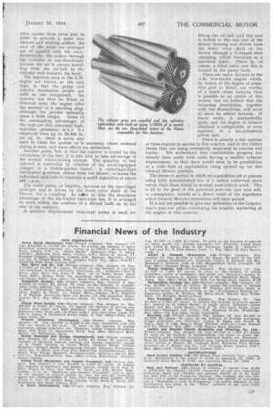
The water pump, or impeller, operates on the centrifugal principle and is driven by the lower rotor shaft of the blower, via a coupling. In miler to take the maximum advantage of the six-bladed vane-type fan, it is arranged to work within the confines of a shroud built on to the rear of the radiator.
A positive displacement vane-type pump is used for lifting the oil fuel, and this unit is bolted to therear end of the blower housing and driven from the lower rotor shaft of the blower through a I.1-shaped steel stamping, which functions as a universal joint. There is, of 2ourse, a relief valve and this is Located in the pump body.
There are many features in the G.M. two-stroke engine which, by reason of the degree of attention paid to detail, are worthy of a much closer analysis than is possible in an article of this nature, but we believe that the foregoing description, together with the illustrations, will serve to show its salient features. It starts easily, is Mechanically quiet, and the degree of balance obtained is comparable, or even superior, to a six-cylindered petrol unit.
There is. already a fair number of these engines in service in this country, and in the United States they are being extensively employed in coaches and lorries. We understand that considerable progress has already been made with units having a smaller, cylinder displacement, so that there would seem to be possibilities of a wide field of exploitation being opened up for this General Motors product.
The forms of service in which its capabilities are at present being fully demonstrated are of a nature somewhat more severe than those found in normal road-vehicle work. This is all to the good of the potential post-war user who will, in consequence, benefit as a direct result of the experience which General Motors Corporation will have gained.
It is not yet possible to give any indication of the Corporation's post-war plans concerningthe possible marketing of the engine in this country.