


Semi-automatic Fluid Transmission
Page 32
If you've noticed an error in this article please click here to report it so we can fix it.
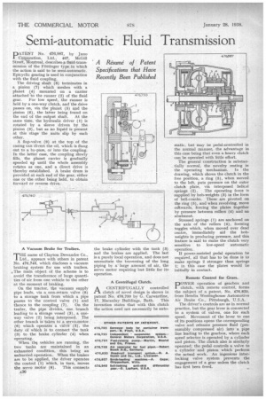
PATENT No. 476,887, by Juno Corporation, Ltd., 407, McGill Street, Montreal, describes-a fluid,tra.nsmission Of the Ftittinger type in which the action is said to he semi-automatic. Epicyclic gearing is used in conjunction with the fluid coupling.
The driving shaft (8) terminates in a pinion (7) which meshes with a planet (4) mounted on a carrier attached to the runner (2) of the fluid gear. For low speed, the runner is held by a one-way clutch, and the drive passes on, via the planet (5) and the pinion (6), the latter being found on the end of the output shaft. At the same time, the hydraulic driver (1) is rotated by a sleeve driven by the pinion (3), but as no liquid is present at this stage the units slip by each other.
A flap-valve (9) at the top of the casing can divert the oil, which is flung out to a by-pass, or into the coupling. In the latter case, the coupling slowly fills, the planet carrier is gradually speeded up until the whole assembly rotates as one, and a direct drive is thereby established. A brake drum is provided at each end of the gear, either one or the other being held, to obtain forward or reverse drive.
A Vacuum Brake for Trailers.
THE name of Clayton Dewandre Co., Ltd., appears with others in patent No. 476,740, which discloses a vacuum braking system for use with trailers. The main object of the scheme is to avoid the transference of large quantities of air from one vehicle to the other at the moment of braking.
On the tractor, the vacuum supply pipe leads, via a non-return valve (8) to a storage tank from which a pipe passes to the control valve (1) and thence to the coupling (7). On the trailer, the pipe divides, one branch leading to a storage vessel (3), a oneway valve (2) being interposed. The other branch is taken to a servo-motor (6) which operates' a valve (5), the duty Of which is to connect the tank (3) to the brake cylinder (4) when operating.
When the vehicles are running, the two tanks are maintained in an exhausted condition, this being an unhurried operation. When the brakes are to be applied, the driver operates the control (1) which, in turn, moves the servo motor (6). This connects
A36 the brake cylinder with the tank 3) and the brakes are applied. The last is a purely local operation, and does not necessitate the traversing of the long piping by a large amount of air, the servo motor requiring but little for its operation.
A Centrifugal Clutch.
ACENTRIFUGALLY controlled clutch of novel design is shown in patent No. 476,750 by G. Carwardine,
17, Macaulay Buildings, Bath. This invention states that with this clutch the action need not necessarily he auto matic, but may be pedal-controlled in the normal manner, the advantage in this case being that even a heavy clutch can be operated with little effort.
The general construction is substantially normal, the novelty resting in the operating mechanism. In the drawing, which shows the clutch in the free position, a ring (5), when moved to the left, puts pressure on the outer clutch plate, via interposed helical springs (2). The operating force is supplied by hob-weights (3) in the form of bell-cranks. These are pivoted on the ring (5), and when revolving, move otitwards, forcing the plates together by pressure between rollers (4) and an abutment.
Stressed springs (1) are anchored on the axis of the rollers (4), forming toggles which, when moved over dead centre, immediately aid the bobweights in producing pressure, and this feature is said to make the clutch very sensitive to low-speed automatic operation. If power-assisted pedal operation be required, all that has to be done is to make springs 2 stronger than springs 1; in this case the plates would be initially in contact.
Remote Control for Gears.
DOWER operation of gearbox and I clutch, with remote control, forms the subject of a patent, No. 476,820, from Bendix Westinghouse Automotive Air Brake Co., Pittsburgh, U.S.A.
The driver's controls are as in normal practice, but the gear lever is connected to a system of valves, one for each speed. Movement of the lever to one of its positions opens the corresponding valve and releases pressure fluid (presumably compressed air) into a pipe line leading to the gearbox, where each speed selector is operated by a cylinder and piston. The clutch also is similarly operated; the pedal controls a valve to a cylinder and piston which perform the actual work. An ingenious interlocking valve system prevents the engagement of a gear unless the clutch has first been freed.