


Patents Completed.
Page 20
If you've noticed an error in this article please click here to report it so we can fix it.
Complete specifications of the following patents will be sent to any address in the United Kingdom upon receipt of eightpence per copy at Sales Branch, Patent Office, Holborn, W.C.
TIRES. — Worby Beaumont. — No. 28,517, dated 27th December, 1907.—This invention relates to tires for motor vehi‘cles and has for its object to construct a tire i a such manner as to minimise the liability of side-slipping. The tire is formed with ridges or headings at each side of the tread in such position that it will not be subjected to the same compression as the load-carrying portion of the tire, but will he pressed lightly into contact with the road. These headings are formed with sharp edges so that, when
side-slipping occurs, they will act as squeegees and the greasy matter art the road will be cleared from the path of the load-carrying portion of the tire, and will thus allow the tire to regain Its grip on the road. In the application of this invention to pneumatic tires, in which comparatively little wear in a radial direction is permissible, the edge of the tread is formed as a laterally-projecting fillet or rib which is practically unsupported in a vertical direction, or against the pressure due to the load. On solid tires, on which a large allowance for wear has to be made, the projecting ribs are arranged in a special manner,
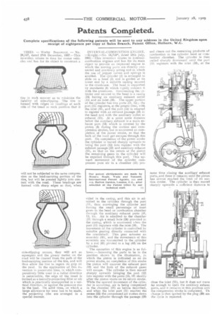
INTERNAL-COMBUSTION ENGINE. —Knight—No. 14,729*, dated 18th July, 1905.—This invention relates to internalcombustion engines and has for its main object to provide an improved engine in which the moving parts are directly connected and positively acting and in which the use of poppet valves and springs is avoided. The cyhader (1) is arranged to slide on a heed (2) and is guided at its lower end by a suitable casting secured to the crankcase. The head is supported by standards (8) which rigidly connect it with the crankcase. Surrounding the cylinder and secured to the head is a casing (14) having an auxiliary exhaust outlet
(15) and an inlet (16). The upper portion of the cylinder has two ports (11, 12); the port (11) registers, at the proper mime, with the inlet (16), and the port (12) is adapted to register with an exhaust passage (18) in the head and with the auxiliary outlet or exhaust (15). At a point some distance below the auxiliary exhaust is a main exhaust port (13) which is covered by the piston (3) during the suction and compression strokes,-but is uncovered on completion of the power stroke, so that the bulk of the inert gas escapes through this port. On completion of the power stroke the cylinder is moved sharply upwards to bring the port (12) into register with the exhaust passage (18) and auxiliary exhaust (15), so that on the return of the piston the remaining gases in the cylinder will be expelled through this port. This upward movement of the cylinder compresses pure air in a chamber (21) pro vided in the casing, and this air is admitted to the cylinder through the port (11), thus scavenging the cylinder and forcing the small percentage of inert gases in the head or combustion chamber through the auxiliary exhaust ports (18, 12, 1.5). Air is admitted to the chamber 121) through a small hole (24) provided in the casing, which is uncovered when the port (11) registers with the inlet {16). The movement of the cylinder is controlled by suitable gearing directly connected with the crankshaft. This gear actuates an eccentric (45), and the movements of this eccentric are transmitted to the cylinder by a rod (41) pivoted to a lug (43) on the cylinder.
The operation nf this engine is as follows :—Assuming the parts to be in the position shown in the illustration, in which the piston is indicated as on its power stroke, on completion of this stroke the piston will uncover the exhaust port (131 and the bulk of the exhaust gases will escape. The cylinder is then moved sharply upwards bringing the port (12) into register with the ports (15, 18) shortly after the piston starts on its return stroke. While the upward movement of the cylinder is occurring, air is being compressed in the chamber (21) as before described, and when the inlet port (11) reaches the recess (22) the compressed air rushes down into the cylinder through the passage (23)
and clears out the remaining products of combustion in the cylinder head or combustion chamber. The cylinder is then pulled sharply downward until the port (11) registers with the inlet (16), at the same time closing the auxiliary' exhaust ports, and there it remains until the piston has almost reached the limit of its suction stroke. The cylinder is then moved sharply upwards a sufficient distance to
close the inlet (11), but it does not trave far enough to open the auxiliary exhaus ports, and it remains in this position unti the compression stroke is completed. Th charge is then ignited by the plug (39) am the cycle is repeated.