


• We have received a number of requests to include
Page 104
Page 105
Page 106
Page 107
If you've noticed an error in this article please click here to report it so we can fix it.
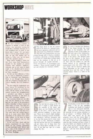
a Volvo in this series, one operator saying he would like it included "because it's a very techAical sort of truck, if you know what I mean." It's our intention to cover as many models as possible on the UK market but to return to Volvo, yes, we do know what this operator means.
Many fitters tackling a Volvo for the first time find themselves puzzled by the number of control systems with switches, inhibitors, solenoids and so on. each of which ought to be checked and if necessary reset if the truck is to function as Volvo intended.
To find out how different a Volvo is, we went to Maidstone Commercials at Aylesford, near Maidstone, Kent, to go through these checks v,ith the company's foreman fitter on Volvo's flagship, the F12 Globetrotter.
The first thing he emphasised was that there is nothing to be frightened about in servicing a Volvo. All the checks on the various control systems are straightforward — provided you follow a logical checking procedure as laid down in the Volvo workshop manual.
The servicing checks are not difficult, and the manual is very clearly laid out, but many of the procedures will be unfamiliar to fitters trained on other makes of truck. One thing became perfectly clear — it is unwise to try guessing at settings, or trying to arrive at them by trial and error. You must have the setting figures, and as in some cases these differ depending on the options for a particular vehicle, so we have in some cases here referred you to the workshop manual.
At the very least, check with the service department of your Volvo dealer for the settings appropriate to your particular truck. Better still, get a copy of the manual and insist that your fitters consult it.
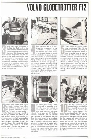
by Peter Wallage This large dryer in the air system used to be listed as a optional extra, but most operators ordered it and we understand from Maidstone Commer cials that most Globetrotters are now coining through with it fitted as standard. It contains a dessicant, or drying material, in the form of a small white crystals which take up the moisture in the air as it passes through. At regular intervals — more frequently in prolonged wet weather — these crystals should be taken out and checked for moisture content. As well as checking the thickness of the lining through the usual holes in the backplate, the selfadjusting of later Z-cam brakes on the front axle of the Globetrotter sliould be checked by measuring the stroke of the piston. The distance from the face of the chamber to the clevis should be measured first with the brakes off, then with the brakes on, and the stroke arrived at by subtracting one measurement from the other. The correct stroke will be between 30rnm and 50mm depending on the length of the operating lever and the type of brake chamber fitted. There is a table in the manual. Some fitters make the mistake of checking the fluid level in the power-assisted steering reservoir without having the engine running. Very often this gives a false reading as the level drops when you start the engine and the pump circulates the fluid. The level should be checked with the engine running. There is a dipstick behind the filler cap, and though the cap is large, the reservoir is somewhat tucked away on the nearside of the engine, so you may need a funnel to avoid spilled fluid, but be careful not to overfill. Many operators like to fit extra air-operated accessories to the Globetrotter — quite a number are available from Volvo dealers — but in some fitters are unsure where to tap into the air system. In a few cases they take the air supply off inappropriate points to go to the trouble of making up brackets for the valves. This is unnecessary as Volvo has provided a take-off point alongside the engine on the nearside chassis member, complete with a pre-drilled bracket and the necessary electrical leads. The valves in the accessory kit will bolt straight on, but remember to fit the 0-rings in the kit or you will get leaks.
There used to be a manual engine stop control on the Volvo F12, but this has now been replaced by an automatic key-operated control so that the engine stops as soon as you switch off. The adjustment for this control is a threaded rod with ball joints at the ends, and it is tucked away on the nearside of the engine where it is not obvious — and none too easy to reach. It seldom gives trouble, but a few cases of poor starting, or even non starting, have been traced to a wrongly set rod. You will find the correct setting dimensions in the manual.
The fuel injector pump on the Ti.) 121 F engine is shaft driven on the nearside of the block, and there are two flexible steel discs in the drive, rather like the old fabric universal couplings, of many years ago. These are to absorb slight misalignment in the mountings because of production tolerances, bolt-hole clearances and so on, but this means that in some cases they have to flex. Maidstone Commercials has had the odd case of a breakdown call out where one of these discs has failed, so check them carefully on a service. If you find any sign of a crack, change the disc. Overhauling a turbo blower is defi
Initely a job for the specialist workshop and should be required only at very infrequent intervals. Some operators, however, lessen the intervals by not paying attention to the air cleaner — or fitting a cheap nonVolvo filter that doesn't do its job properly, even with the correct filter it pays to keep an eye on the condition of the turbo. It takes only a few minutes to undo the inlet trunking and have a look. tf the rotor blades are chipped or pitted, or if the rotor can be moved from side to side, or back and forth — check with your fingers — grit has been getting through the filter.
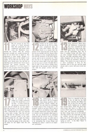
Unlike many trucks which have a red-marker-in-a-tube type indicator to let the operator know when the air filter is becoming blocked, the F12 has a pressure sensing — or rather depression-sensing — switch in the air inlet trunking just inboard of the main air filter casing. lithe manifold depression becomes too high, a warning light shows in the cab. In normal operation the switch is never called upon to work, and there is a danger that it could fail without the driver being aware of it. Volvo dealers have a service tool which can draw a depression to check it.
The exhaust brake on the TO 121 F engine will be unfamiliar to fitters who have not worked on Volvos before. In place of the more usual restrictor flap in the exhaust, Volvo uses an EP (Exhaust Pressure) Regulator. This can vary the back pressure of the exhaust and has three functions. It acts as a normal exhaust brake with a control button on the floor of the cab, it is connected to operate whenever the handbrake is applied and it is also connected to a switch in the cab to use it as a smoke emission control in traffic when the engine is cold. Once again, cleaning and service procedures are in the manual. The EP Regulator is air operated and is controlled by two solenoid valves on the offside of the engine. The front switch operates the control as an exhaust brake, the rear one as the smoke emission control. There is an adjustment, and once again the setting for this, checked with gauges, is given in the manual. However, as a check that the valves are working, take the electrical connection off each one in turn while the engine is ticking over. With a cold engine you should see a reduction in smoke, and a change in exhaust note at any time with the brake. The air system on the F12 works at a lower pressure than that generated by the compressor and trucks often come into Maidstone Commercial for service with the system pressure wrongly set, usually because fitters do not know how to adjust it. The adjustment is quite simple, though it is rather tucked away on the offside of the engine. If you take the top off the cylindrical valve shown here you will find an adjusting screw and lock nut. Screw out to increase the system pressure. The pressure should be 7 to 8 bar (nearer 8 than 7), but you don't need extra gauges, you can check with the gauges in the cab. Setting up the power steer-. ing box on the F12 is a little more complicated than on some other makes. The first check is to ensure that the cheeks of the universal joint at the top of the box are parallel with the chassis when the steering is in the straight-ahead position and the geometry of the front wheels (toe-in, and so on) is correctly set. Then the box has to be adjusted for pressure by the two volves right at the front which are not too easy to reach. Possibly this is just as well, as the correct setting (once again refer to the manual) can be obtained only with the proper service tool and gauges.
Some operators' fitters have told Maidstone Commercials they have searched for ages looking for a fault in the stoplights circuit. They check the bulbs and the appropriate fuse, but if there is nothing wrong with these they are often stumped because they cannot find the stop light operating switch. The cables disappear into the loom and don't appear to come out anywhere. Search no further. The switch is so easy to get at it is often overlooked. It lives on the footbrake valve in the cab, and the usual checks with a meter will soon reveal any fault.
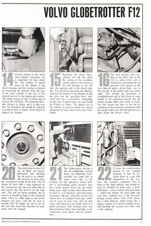
Ljorrect setting of the clutch 'lave-cylinder operating rod Is important for long clutch life. The cylinder is tucked away on the offside of the clutch housing, and the setting is checked by measuring the distance from the face of the slave cylinder to the face of the locknut nearest to the spring and washer. The initial setting for this is 45mm, but in service this will drop. The minimum allowable distance is 32mm, and if it falls near this the threaded rod should be adjusted to bring it back to 45mm. Don't forget to tighten the locknut.
Resetting the clutch slave cylinder rod will also affect the setting of the overdrive control which is low down on the bell housing on the offside, the opposite side to the clutch cylinder. You check by measuring the distance between the bottom of the plunger on the air valve and the operating lever, indicated here by a screwdriver. Depending on the type of clutch fitted, the gap should be 9.5mm to 13mm. The figures are in the manual, or you can obtain the correct dimension for your clutch from your Volvo dealer. The load sensing valve setting on the drive axle of the F12 is adjustable and is checked by measuring the air pressure with gauges at the two take-off points shown here, one at the top left of the picture and one centre right. The setting up procedure is straightforward and is laid down at some length in the workshop manual, but the actual settings differ from truck to truck. For this reason you have to use the instructions in the manual in conjunction with the graph which you will find printed on a plate inside the driver's door.
. The air pressure to the
brakes of a trailer connected to the F12 should have a 0.2 bar bias — in other words the air pressure measured at the suite take-off should be 0.2 bar higher than the pressure to the Volvo's brakes. The trailer air pressure is adjusted by this valve. Underneath the valve you will find a cover with a circlip. Take this off and you will find the adjusting screw inside. Connect a pressure gauge to the suzie take-off behind the cab, apply the brakes and, with full air pressure, adjust the valve so that the gauge on the suzie takeoff reads 0.2 bar higher than the cab gauge. The Globetrotter is fitted with Volvo's SR 70 12-speed range-change gearbox, and to prevent anyone ruining the box and clutch by attempting to change range at the wrong time — for example, trying to go from 12th to 6th at speed — there is an inhibitor switch. Like the air-filter depression switch, this inhibitor switch is never normally called upon to work, but you should have its operation checked with the service tool by a Volvo dealer from time to time to make sure it works should you need it. Trying to check it by attempting the wrong change and "listening for noises" could be an expensive procedure.
There is a dipstick on the top of the oil tank for the fluid
that operates the lifting rear 110 axle on the F12, but the tank
needs topping up so seldom that though fitters check the level they often forget that there is a filter in the system which ought to be checked at the same time and renewed periodically — the filter change times are in the manual. The filter itself is the usual type of canister oil-filter element and is under the filler cap of the tank where it is held in position by a spring on the cap. Check the spring as well — if the filter "floats" it cannot do its job. The front hubs on the F12 are oil filled, not grease lubricated, and checking the oil level is so simple. All you have to do is clean the transparent centre of the hub. The oil should be level with a ring engraved on the transparent cap, but you often find on new trucks that the level is on the high side. This will not harm anything, but in service it should be kept to the engraved mark. There is a filler plug on one of the hexagon nut faces, and the oil used is usually SAE 30 engine oil, but to be on the safe side check the viscosity for your truck with the manual. The Globetrotter cab has a full air-conditioning system fitted, but Maidstone Commercials has found that in some cases this is not working and the operator's fitters have left it nonworking either because they have heard stories about the gas inside being nasty stuff, or they don't know how to check it. It is checked, and if necessary recharged with gas, using the service tool shown here. It contains Freon gas, which can be nasty in your eyes, and can also cause cold burns on your hands when it is under pressure. The foreman here was demonstrating rather than checking, or he would have worn gloves and eye protectors.
If your air-conditioning system is not working properly, it may be because there is a gas leak somewhere in the system. The system's condenser lives in front of the main radiator, and should always be checked for leaks after a frontend shunt — even a minor front-end shunt — which has broken the front grille and may have strained one of the air-conditioning system joints. Your Volvo dealer has a leak detector which beeps like a geiger counter if it detects leaking freon, and checking the system over takes only a few minutes.