


Coil ignition, 1
Page 42
If you've noticed an error in this article please click here to report it so we can fix it.
GNITION faults are the most frejuent cause of breakdowns with petrol-engined vehicles. It is also rue to say that the subject which notor vehicle apprentice stulents have most difficulty in unerstanding is motor vehicle lectrics.
Perhaps this is because lectricity can't be seen and luch of what is taught has to be )ken for granted. An engine onnecting rod, for instance, or n axle crown wheel and pinion )e parts can be handled and ieir function and the way in ,hich they operate can be easily emonstrated — but this isn't so
ith electrical components.
The type of vehicle using coil nition is generally fitted with a ?-volt battery, yet a voltage of )out 8,000 volts is needed to .oduce a spark at the sparklingug points under combustion lamber conditions.
A four-stroke four-cylinder enne requres a spark at each cylder once for every two revolums of the engine. Considering e four cylinders, that is two arks for each engine rev. This means that at maximum engine revs, say 6,000 per minute, 1,200 sparks are needed every minute or 200 every second.
Also, each spark must be directed to the right cylinder and it must arrive there at precisely the right moment.
Before we can examine exactly how these demanding requirements are met a little basic electrical theory is necessary. First, when a current flows in a circuit, a magnetic field is created around the conductor through which the current is flowing. Secondly, when a magnetic field moves across a closed circuit a current is induced in the circuit.
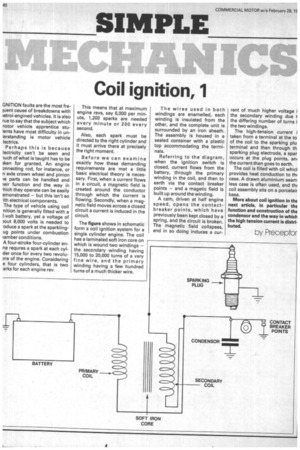
The figure shows in schematic form a coil ignition system for a single cylinder engine. The coil has a laminated soft iron core on which is wound two windings the secondary winding having 15,000 to 20,000 turns of a very fine wire, and the primary winding having a few hundred turns of a much thicker wire. The wires used in both windings are enamelled, each winding is insulated from the other, and the complete unit is surrounded by an iron sheath. The assembly is housed in a sealed container with a plastic top accommodating the terminals.
Referring to the diagram, when the ignition switch is closed, current flows from the battery, through the primary winding in the coil, and then to earth via the contact breaker points — and a magetic field is built up around the winding.
A cam, driven at half engine speed, opens the contactbreaker points, which have previously been kept closed by a spring, and the circuit is broken. The magnetic field collapses, and in so doing induces a cur
rent of much higher voltage i the secondary winding due t the differing number of turns i the two windings.
The high-tension current i taken from a terminal at the to of the coil to the sparking plu terminal and then through th sparking plug electrode, a spar occurs at the plug points, an+ the current then goes to earth.
The coil is filled with oil whicl provides heat conduction to thi case, A drawn aluminium seam less case is often used, and th( coil assembly sits on a porcelair base.
More about coil ignition in the next article, in particular the function and construction of the condensor and the way in which the high tension current is distributed.
oy Preceptor